
The input circuit common mode noise suppression microphone amplifier with balance

The circuit design focuses on optimizing the common mode signal rejection ratio through the careful selection and configuration of transformers and operational amplifiers. The use of a THS-2 transformer with a specified impedance ratio enhances the performance, particularly in applications requiring high fidelity and low noise levels. The step-up ratio derived from the transformer’s turns ratio plays a crucial role in determining the voltage gain, which is essential for ensuring that the signal remains strong enough for further processing.
Resistance values in the circuit are critical, as they directly influence the frequency response and overall performance of the transformer. The low-pass filter implemented serves to minimize high-frequency noise, allowing for clearer signal transmission. The choice of the OP37 operational amplifier is significant due to its low noise characteristics, which are vital in sensitive applications where signal integrity is paramount. The configuration of the amplifier in a closed-loop manner ensures stability and enhances the frequency response, making it suitable for high-performance audio or data acquisition systems.
In cases where a high offset voltage is present, the inclusion of a series capacitor is recommended to mitigate potential issues caused by DC offsets, ensuring that the signal remains within the operational limits of the amplifier. This careful consideration of component selection and circuit configuration is essential for achieving optimal performance in electronic systems that require high levels of signal integrity and noise reduction. Because the common mode signal rejection ratio depends on the input transformer, it should be used or homemade good balance transformer (It should be noted l frequency increase s, the balance will fall), is determined to consider the transmission frequency range boost ratio. Step-up ratio is primary to secondary turns ratio. Terminal can also be used to represent the square root of the impedance ratio. The circuit uses a utility available on the market THS-2 transformer impedance ratio of 6000: iookQ, so the boost ratio:/1 xo Lily F4, this kind available 12dB voltage gain from the input conversion noise this point look relatively favorable. Resistance R, and in the sub-Yi across the transformer, it seems no need to use iokfl, but the frequency characteristics of the transformer with a resistance value becomes, so the frequency characteristics measured to determine a post- chu t, cl high noise suppression is a low-pass filter for high inhibition effect depends dry cl, Zhang Rz available plus the equivalent output resistance is obtained.
OP zoom uses a closed-loop frequency characteristics of a good low-noise type OP37, straight surprised coupling. If you use a high OP amplifier offset voltage, should the series with a roar of dozens of micro-ho capacitance mouth
Related Circuits
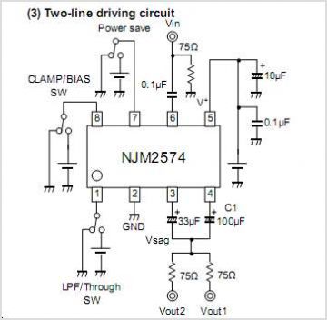
The NJM2670 is a general-purpose 60V dual H-bridge drive integrated circuit (IC). It features a pair of H-bridges, a thermal shutdown circuit, and an alarm output. The alarm output is capable of detecting application issues, thereby significantly enhancing system...

This circuit must be used between the drive voltage of such a transformer and track. On JP1, the transformer is connected to JP2, the rails are connected to JP3, is a TTL "High" position when there is a tax...
This simple circuit generates narrow pulses at a frequency of approximately 700-800 Hz. The pulses, which contain harmonics extending into the MHz range, can be injected into audio or radio-frequency stages of amplifiers and receivers for testing purposes. A...
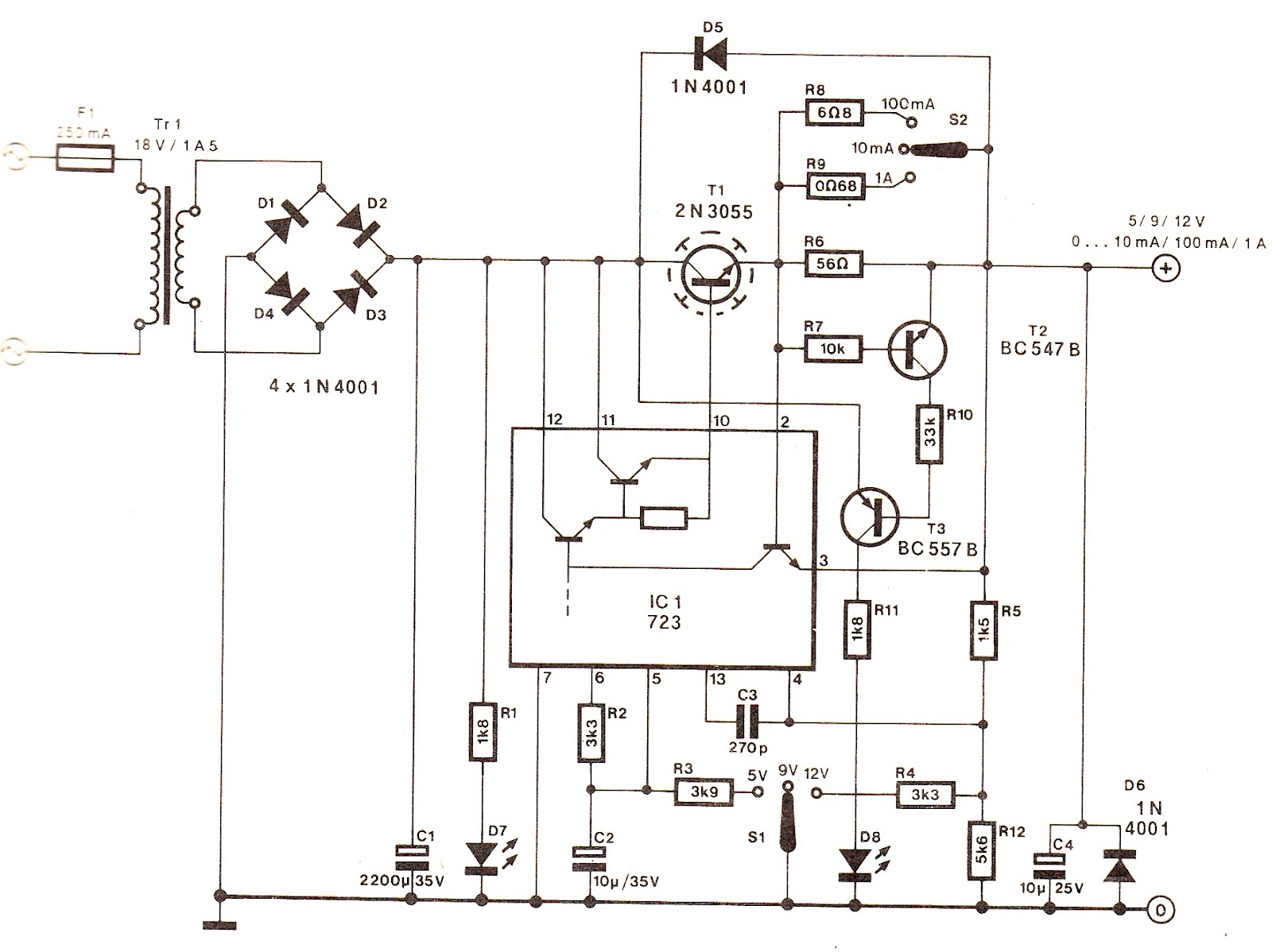
The output voltage can be increased easily by placing a resistor in parallel with Ra until it reaches precisely 5.0 V. Switches S1 and S2 are preferably SPDT types with a center position, but three-way rotary switches can also...
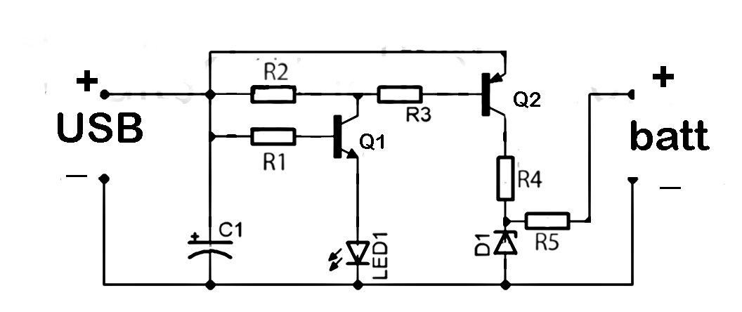
This document discusses the series used in USB connections for charging batteries. The output voltage ranges from 4.7 volts to 5 volts DC, which is suitable for charging mobile phones and other battery types. The circuit described enhances the...
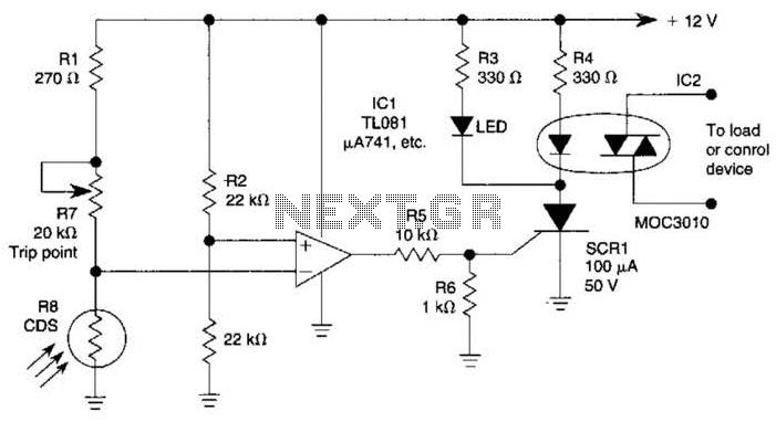
The light-sensitive CDS cell R8 is configured in a bridge circuit with IC1 functioning as a comparator. When light strikes the CDS cell R8, the output of IC1 goes high, triggering SCR1. This action illuminates LED1 and activates opto...