
Humidity detector circuit electronic project

The humidity detector circuit operates by monitoring the resistance between two copper conductors that serve as the sensing element. As humidity increases, moisture accumulates on the copper surfaces, leading to a reduction in resistance. This change is detected by the Schmitt trigger, which is designed to provide a stable output even with noisy input signals. The transistors T1 and T2 form a feedback loop, ensuring that once the circuit is triggered, it remains in that state until it is reset.
The bistable multivibrator configuration allows the circuit to maintain its output state. Capacitor C1 plays a crucial role in defining the timing characteristics of the circuit, influencing how quickly the system can respond to changes in humidity. When the resistance falls below the predetermined threshold, the output at point B transitions to a low voltage, which energizes the relay. This relay can then be used to control larger loads, such as fans, dehumidifiers, or other electronic devices, making this circuit highly versatile for various humidity control applications.
Overall, this simple yet effective humidity detector circuit provides a reliable means of monitoring environmental conditions and automating responses to changes in humidity levels. The use of basic components allows for easy construction and integration into various projects, making it suitable for both educational purposes and practical applications in home automation systems.This humidity detector circuit diagram is very simple and uses few components and can be used for activation of an electronic devices when the detector senses a certain humidity. The sensor is constructed from two pieces of copper placed at a short distance of each other. when the electrical resistance of copper conductors drops below a certain va lue, Schmit trigger built using transistors T1 and T2 switch. Bistable multi-vibrator is flip through C1, so that at point B there is a low voltage (relay triggers). 🔗 External reference
Related Circuits
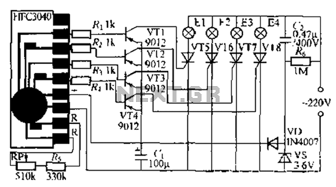
The circuit utilizes a four-way slowly dimming LED driver integrated with iU shoe production and a Qis four flashing lights string controller. The C3484 manifold is specifically designed to operate Ji lights with four lights that flash and slowly...
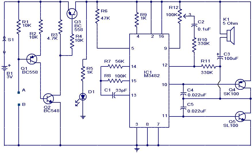
This circuit is a simple musical alarm that generates a tone when water or another conductive liquid touches the two sensor wires provided. It utilizes four transistors and a melody generator integrated circuit (IC) M3482. When water bridges the...
The metal detector circuit comprises several key components, including a power circuit, a sine wave oscillator, a PLL (phase-locked loop) circuit, and a hybrid amplifying circuit. The power circuit is made up of batteries GBI and GB2, filter capacitors...
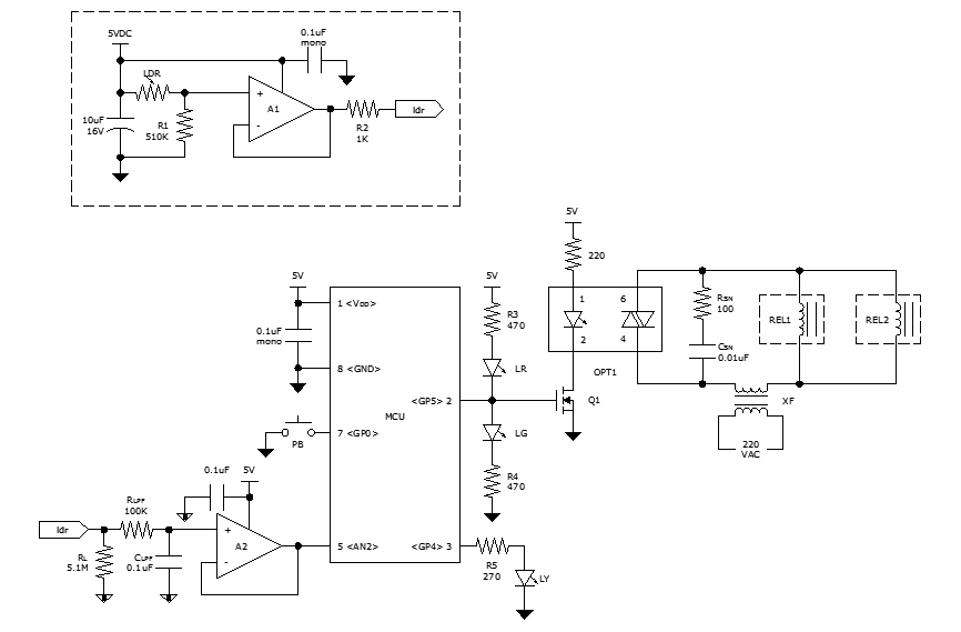
While discussing an all-linear automatic night light circuit, it was mentioned that an MCU-based Automatic Night Light Controller (ANLC) was being tested. The firmware has been tweaked since then. Recently, the sensor was installed outdoors and connected to control...
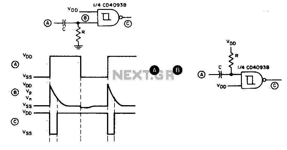
This circuit generates a brief negative-going output pulse in response to each positive-going edge at the input. The input signal is coupled to the circuit through a capacitor (C), and the duration of the output pulse is determined by...
This project utilizes the ISD2560P integrated circuit (IC), which enables the recording of 60 seconds of audio and subsequent playback with high fidelity. The schematic indicates that the input source is an electret microphone. If a dynamic microphone is...