
humidity sensor circuit II

The circuit operates by utilizing a pair of switches, specifically the 14B-12B pair, which controls the connection of the sensor to the summing point of an operational amplifier (labeled as Al). When the switches are opened, the sensor's output is routed through a 1 µF capacitor, allowing the sensor's discharges to influence the summing point. This capacitor serves as a coupling element, ensuring that only AC signals are passed while maintaining a zero average voltage. This is critical for accurate readings, as it prevents any DC offset from affecting the sensor's output.
The average current flowing into the summing point is directly influenced by the humidity-related value of the sensor, which alters the amount of charge delivered over time. This current is balanced by the operation of a switched-capacitor circuit, which effectively integrates the incoming charge packets. The use of a 22M resistor in parallel with the summing point plays a vital role in preventing charge accumulation. If charge were to build up, it could halt the current flow, leading to erroneous readings and circuit malfunction.
The combination of these elements results in a system where the output from the operational amplifier reflects a DC signal that corresponds to the integrated average of the sensor's output. This integrator-like response is essential for applications requiring stable and accurate humidity measurements, as it smooths out fluctuations and provides a reliable representation of the sensor's performance.When the 14B-12B pair opens, 12B is connected to Al's summing point via 13B. The sensor now discharges into the summing point through the 1 µ capacitor. Since the charge voltage is fixed, the average current into the summing point is determined by the sensor's humidity related value. The 1 µ value ac couples the sensor to the charge-discharge path, maintaining the required zero average voltage across the device.
The 22M resistor prevents accumulation of charge, which would stop current flow. The average current into Al's summing point is balanced by packets of charge delivered by the switched-capacitor gives Al an integrator-like response, and its output is dc.
Related Circuits
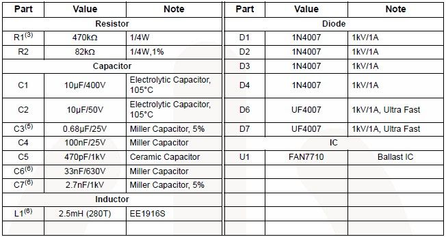
The FAN7710 Ballast Control IC for Compact Fluorescent Lamps, developed using Fairchild's unique high-voltage process and system-in-package (SiP) concept, enables the design of a simple and low-cost fluorescent lamp driver electronic project. The FAN7710 ballast control manages internal high-voltage...
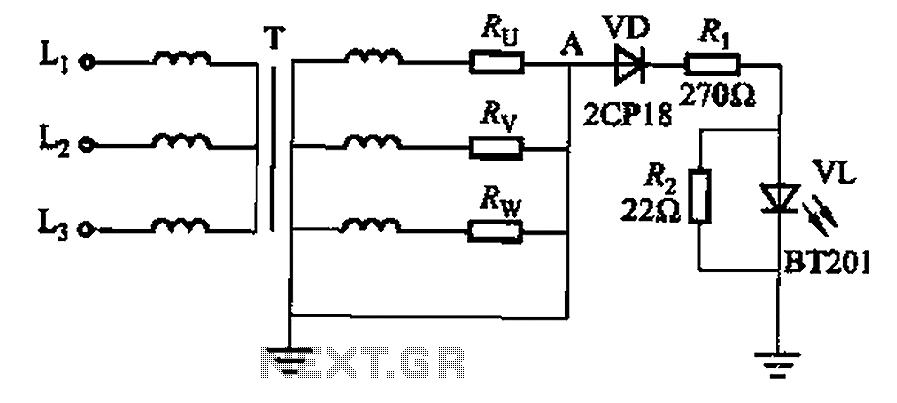
It is well understood that if the power transformer neutral line is disrupted, an unbalanced three-phase load can easily result in overvoltage conditions, potentially damaging electrical equipment such as household appliances and lamps. The neutral circuit alarm system is...
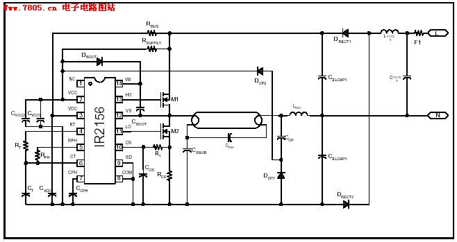
The IR2156 provides a cost-effective solution for fluorescent electronic ballasts. It integrates features such as lighting tube error protection and a programmable working frequency, which includes warm-up, lighting, and continuous operation of the ballast. The IR2156 is a highly integrated...
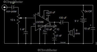
This is a simple low-power audio amplifier circuit capable of producing a power output of 1W. The mono amplifier circuit is built around the LM386 integrated circuit, which operates effectively at low voltages, even below 9V. This low-voltage amplifier...
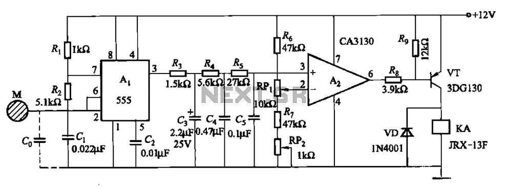
The circuit utilizes a 555 IC in conjunction with capacitors C1, C2, and a metal plate (tablet) M to create a distributed capacitance Co and resistor R1 connected to ground. Resistor R2 forms a self-excited multivibrator, while resistors R3...
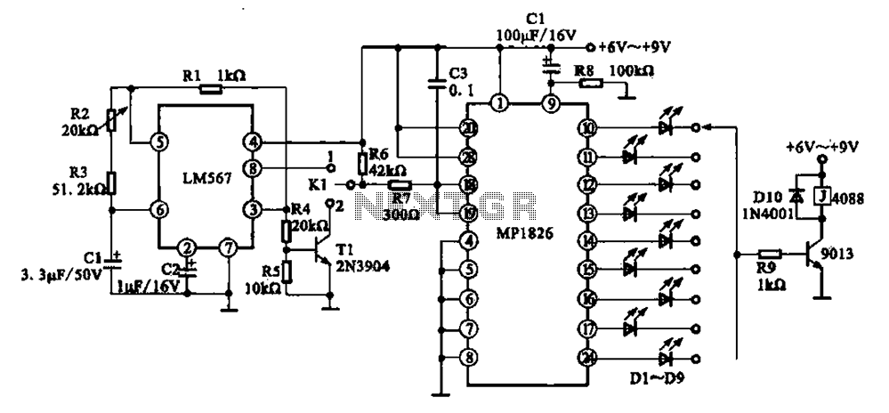
A precision circuit utilizing the LM567 timer, specifically the MPI826, where the LM567 functions as a dual-band oscillator. The MP1826 serves as a divider in the circuit, allowing the output signal from the LM567 to achieve extended timing. The...