
One of the three-phase AC power circuit neutral wire break alarm

The neutral circuit alarm system plays a critical role in protecting electrical devices from potential damage due to unbalanced loads in a three-phase power system. The circuit operates by continuously monitoring the neutral point of the transformer. When the neutral line is functioning correctly, the VL LED indicator remains lit, signaling that the system is operating within safe voltage parameters.
In the event of an unbalanced load, the neutral point may experience a potential shift, leading to an increase in voltage that could harm connected appliances. The alarm circuit is designed to detect this shift and trigger an alert, thus preventing equipment damage. The variable power voltage regulator (T) allows for adjustments in voltage levels, enabling the circuit to adapt to varying load conditions.
The load resistors (Ru, Rv, Rw) are essential components that represent the various loads connected to the power system. Each resistor can simulate different operational scenarios, helping to evaluate the effectiveness of the alarm system under various conditions. The design of this circuit emphasizes reliability and responsiveness, ensuring that any deviation from normal operating conditions is promptly addressed.
Overall, the neutral circuit alarm system serves as a vital safeguard in three-phase electrical systems, providing essential monitoring and alerting functionalities to protect both the infrastructure and connected devices from the adverse effects of unbalanced loads. As we all know, if the power transformer neutral line circuit, and when the three-phase unbalanced load and can easily lead to electrical equipment (such as household appliance s, lamps, etc.) due to overvoltage (neutral point potential shift caused) damage. Neutral circuit alarm circuit is the use of transformer neutral line when following the path, the neutral point potential shift principles and design. Circuit shown in Fig. 13 + 80. When the power neutral line circuit, VL LED light. FIG, T is variable power voltage regulator, Ru, Rv, Rw of the load.
Related Circuits
This relatively simple mixer was designed for three dynamic microphones, but can be re-designed for more or less. Level and tone controls are available to tailor the sound to your needs. More: R1-R3 are level controls. R9 and R11...
This circuit triggers an alarm when its LDR (Light Dependent Resistor) sensor is exposed to light from the sun or a lamp. A 555 astable multivibrator is utilized to generate a tone of approximately 1 kHz upon detecting light....
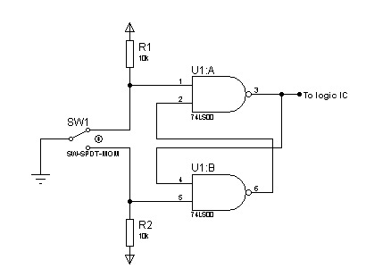
In most digital electronics projects that utilize various types of switches, switch bounces are frequently encountered. These are additional glitches that occur following the actual operation of the switch. These small pulses can disrupt the proper functioning of the...
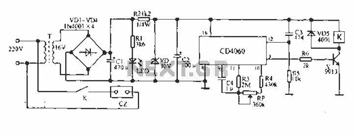
A CD4060 production time controller circuit is illustrated below. It is connected in such a way that R5 and C3 form a differential circuit to create a delay time from the start. Under the influence of the oscillating signal,...
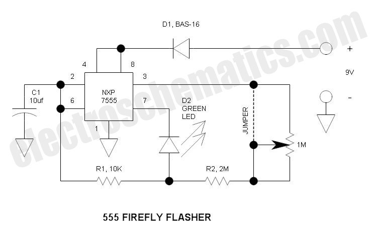
This circuit operates similarly to a standard 555 astable timer, with the distinction that the LED is integrated into the capacitor reset path. Consequently, when pin 7 discharges capacitor C1 to ground, a relatively high current flows through the...
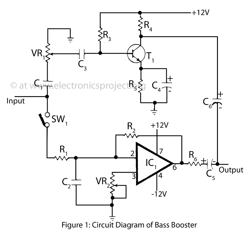
The bass booster featured on this website enhances the beat frequency while maintaining the integrity of the high-frequency response. The circuit diagram for the bass booster, along with various radio circuits, is also provided. The bass booster circuit operates by...