
Hydrogen Generator 555 Timer Pulse Width Modulation Circuit

The hydrogen generator circuit utilizing a 555 timer operates by controlling the duty cycle of the PWM signal to regulate the electrolysis process. The 555 timer is configured in astable mode, producing a continuous square wave output. This output is fed to an electrolytic cell, where water (H2O) is split into hydrogen (H2) and oxygen (O2) gases through the application of an electric current.
The circuit design includes the following components: a 555 timer IC, resistors, capacitors, and an electrolytic cell consisting of two electrodes submerged in water. The resistors determine the frequency and duty cycle of the PWM signal, while the capacitor helps in stabilizing the output waveform. The duty cycle can be adjusted by varying the values of the resistors, enabling the user to control the amount of hydrogen produced.
Power supply requirements for the circuit typically range from 5V to 15V, depending on the specific design and components used. The electrolytic cell must be constructed from materials that are resistant to corrosion, such as stainless steel or graphite, to ensure longevity and efficiency.
Safety precautions should be taken when working with hydrogen, as it is highly flammable. Adequate ventilation is necessary, and the circuit should be housed in a non-combustible enclosure to prevent any fire hazards. The generated hydrogen can be collected and utilized for various applications, including fuel cells or combustion engines, demonstrating the practical utility of this PWM-controlled hydrogen generator circuit.How to Make a Hydrogen Generator 555 Timer Circuit PWM. This Pulse Width Modulation (PWM) Circuit could Produce Hydrogen on Demand.. 🔗 External reference
Related Circuits
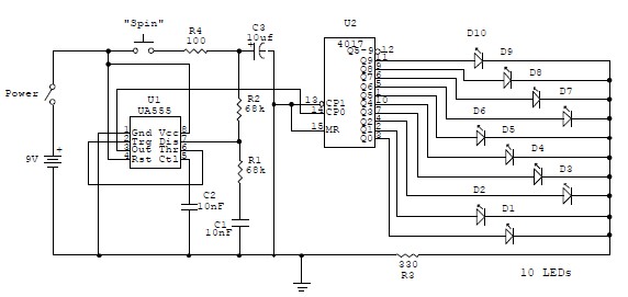
This electronic circuit is a simplified version of an electronic roulette game, utilizing the 4017 integrated circuit (IC), which functions as a 10-stage decade counter/divider. It is driven by a versatile 555 IC configured as a voltage-controlled oscillator (VCO)....
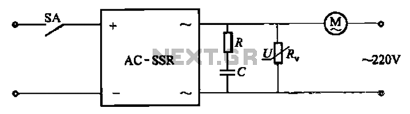
The circuit illustrated in Figure 3-13 is an RC surge absorption circuit that includes a resistor (R) and zinc oxide varistors (such as MY31, MYH12, MYH20 types, etc.), which serve as an overvoltage protection device. The resistance R is...
Want to add video to your next project? This device uses a PIC16F819 and not much else. Getting 20 characters to a line is possible by using the SPI port to generate video. Neat trick, eh? The character set...
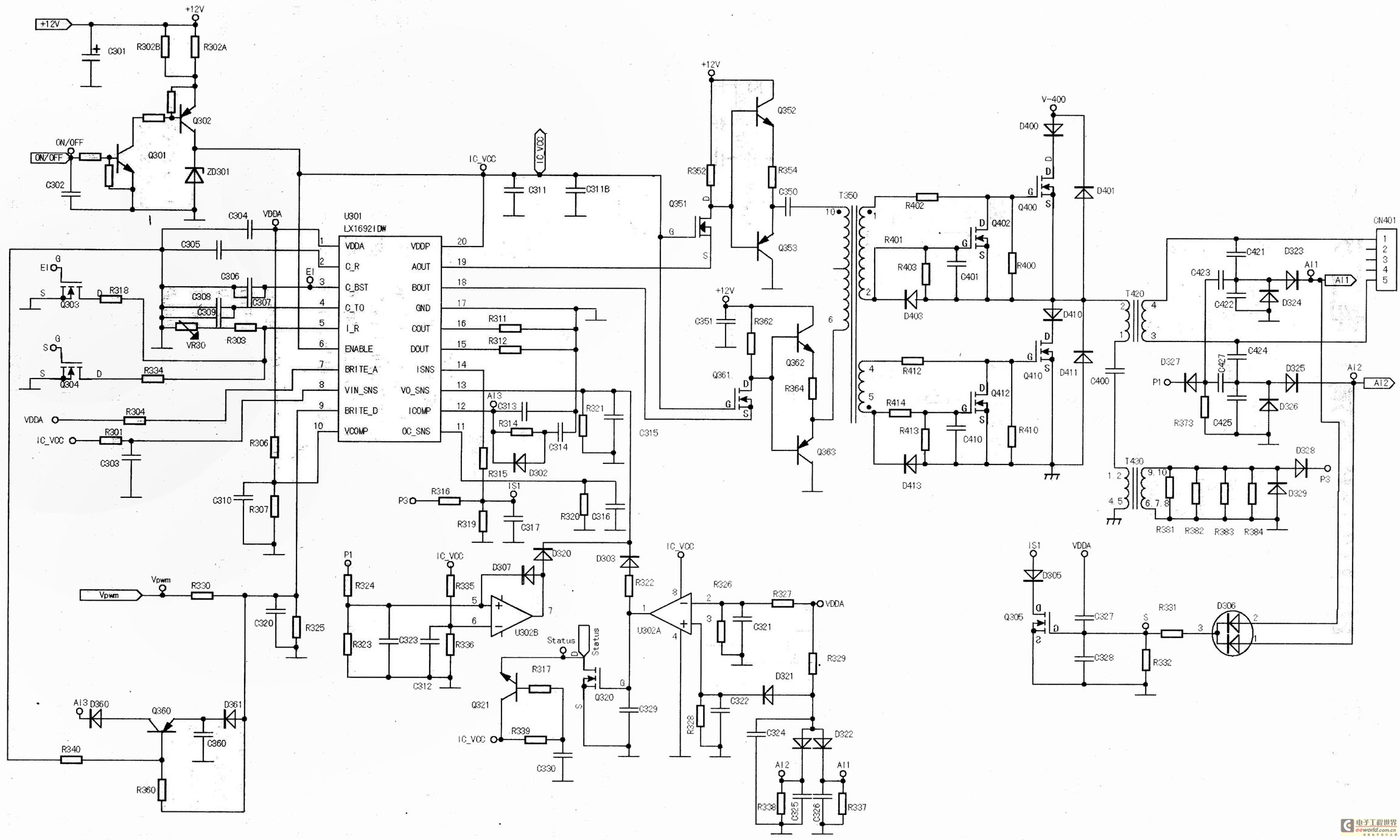
The main component is the LG26 one-inch screens integrated with the FSP107-2PS01 two-in-one electrical power package, which utilizes a direct drive CCFL modulator tube. This setup is compatible with screens from other manufacturers, such as Samsung and AU, but...
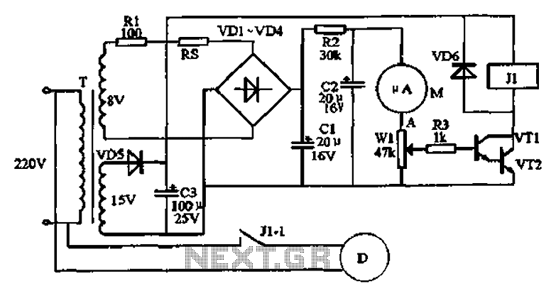
An automatic humidifier can be utilized for humidity control in households, hatcheries, poultry farms, or juvenile poultry houses. When the humidity level falls below 50%, the automatic humidifier activates to maintain a specific humidity level that is beneficial for...
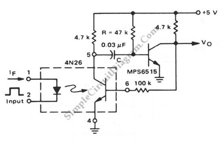
This is a pulse stretcher circuit utilizing an optocoupler. The circuit employs a 4N26 optocoupler in conjunction with a standard one-shot circuitry. The pulse stretcher circuit is designed to elongate the duration of an incoming pulse signal, which is particularly...