
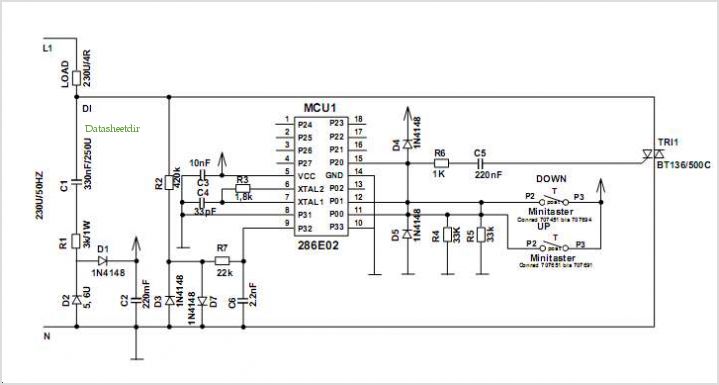
Hysteresis-free phase control circuit

The described circuit utilizes a single RC phase lag network to achieve effective dimming control for lamps. The primary components of this circuit include a resistor (R) and a capacitor (C), which together create a time delay that allows for the modulation of the voltage applied to the lamp. The phase lag introduced by the RC network is crucial in determining the timing of the gate signal, which controls the power delivered to the load.
In operation, the circuit begins with the capacitor charging through the resistor during each positive half cycle of the AC waveform. The voltage across the capacitor gradually increases, and once it reaches a predetermined threshold, it triggers the gate of a semiconductor device, such as a triac or a thyristor. This action allows current to flow to the lamp, thus illuminating it. The degree of dimming is controlled by adjusting the values of the resistor and capacitor, which affects the charging time of the capacitor.
To mitigate the hysteresis effect, which can cause the lamp to flicker or snap on abruptly, the circuit incorporates a mechanism to reset the capacitor to approximately 0 volts at the end of each positive half cycle. This is achieved through the gate lead, which discharges the capacitor quickly, ensuring that it does not retain a significant charge when the next half cycle begins. This reset action maintains smooth operation and prevents erratic behavior of the lamp.
Overall, the described circuit is an efficient solution for lamp dimming applications, leveraging simple components to achieve reliable performance while minimizing undesirable effects such as flickering. Proper selection of the resistor and capacitor values, as well as careful design of the reset mechanism, are essential for optimal functionality.This circuit is intended for lamp dimming and similar applications. It requires only one RC phase lag network To avoid the hysteresis (or "snap-on") effect, the capacitor is reset to approximately 0 volts at the end ofevery positive half cycle using the gate lead.
Related Circuits
Introduction The ignition timing lights commonly used range from simple neon to complex units. Neon timing lights have a drawback due to their low light output, necessitating operation in subdued lighting. This presents a safety hazard, as users tend...
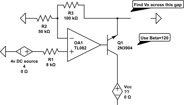
The voltage measured at 12V after the emitter is perplexing, especially when the output from the op-amp is +15V, suggesting a 3V drop across the transistor. This raises questions about the expected gain of 2, which would imply an...
This simple alarm timer circuit is constructed using a 4060 IC, which features an integrated oscillator known for its good stability and relatively wide frequency range. The 4060 integrated circuit (IC) serves as the core component of this alarm timer...
This project involves a straightforward soil moisture detection circuit that utilizes only four components and operates with a 3-volt battery. The circuit is designed to identify the presence of moisture in the soil of any plant and activate an...
The Clapp oscillator is a type of electronic oscillator constructed from a transistor or vacuum tube and a positive feedback network. The Meissner oscillator circuit is a harmonic oscillator that consists of an active electronic element, such as a...
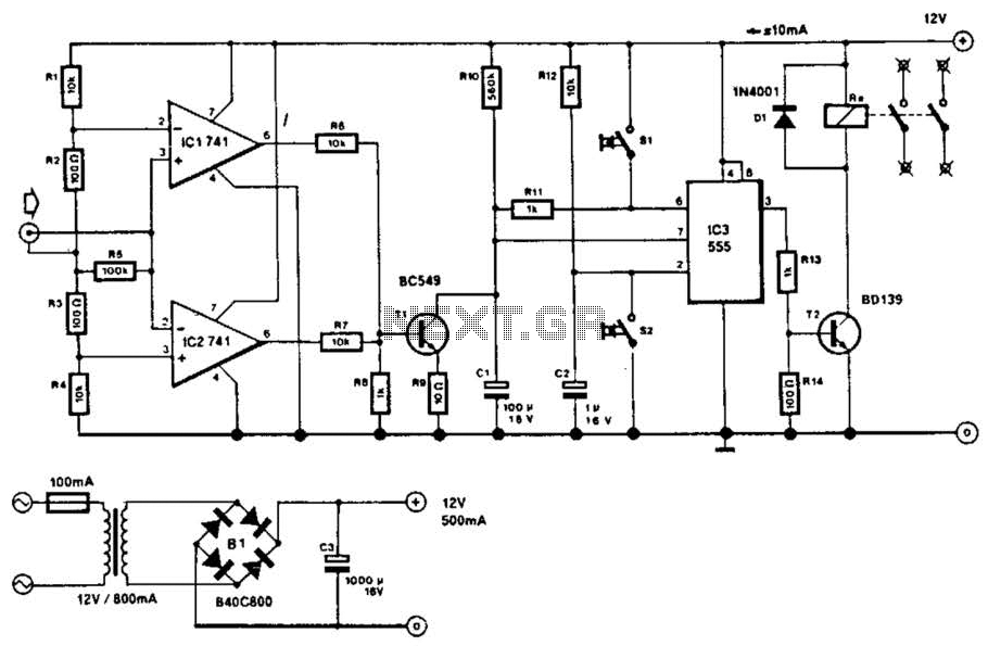
This circuit will disconnect the line supply to audio or video equipment if there has been no input signal for approximately 2 seconds. Switch SI provides manual operation, while switch S2 functions as a reset mechanism. This circuit allows...