
Timer with alarm circuit

The 4060 integrated circuit (IC) serves as the core component of this alarm timer circuit. It combines a high-stability oscillator with a binary counter, making it suitable for timing applications. The oscillator's frequency can be adjusted by selecting appropriate external resistors and capacitors connected to the IC. This flexibility allows the user to set the desired time interval for the alarm function.
The circuit typically operates in the following manner: when powered, the 4060 generates a clock signal at its output pin, which is then fed into a series of flip-flops that divide the frequency. The output from these flip-flops can be configured to trigger an alarm or indicator when the count reaches a predetermined value.
An additional feature of the circuit may include a reset mechanism, which can be implemented using a push-button switch. This allows the user to reset the timer and start the counting process anew. The output can be connected to various types of alarms, such as a buzzer or LED, to signal when the timer has elapsed.
To ensure proper operation, it is essential to provide the correct power supply voltage to the 4060 IC, typically in the range of 3V to 15V, depending on the specific variant used. The design can be further enhanced by incorporating a power-saving feature, such as a low-power mode, which can be activated when the timer is not in use.
In summary, this simple alarm timer circuit utilizing the 4060 IC provides a reliable and adjustable timing solution, suitable for various applications, including reminders, countdowns, and alarm systems.This simple alarm timer circuit is made with 4060 which has an integrated oscillator with a good stability with a relatively wide frequency range. In the c. 🔗 External reference
Related Circuits
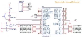
This is the circuit diagram of a line follower/line tracker robot. The circuit is derived from tutorial documentation, which can be downloaded at the end of this article. The line follower robot utilizes eight proximity sensor modules. Each sensor...

The door alarm is designed to be mounted on the door handle and emits a beep when someone touches the door handle from the outside. The door alarm circuit operates on the principle of detecting physical contact with the...
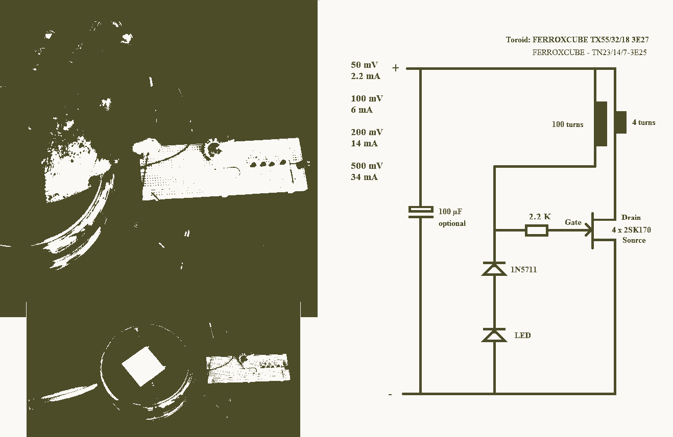
A 25mV Joule Thief powered by a Peltier device that utilizes body heat. The 25mV Joule Thief circuit is an innovative energy harvesting solution that converts the minimal voltage generated by a Peltier device into usable electrical energy. The Joule...
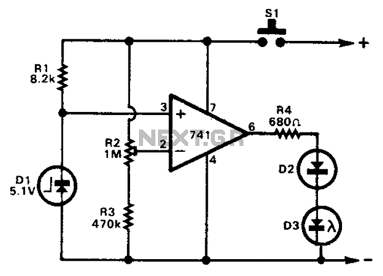
The 741 operational amplifier can function as a voltage comparator. It features a non-inverting input and a Zener-controlled voltage source, with a reference voltage set at 5.1V. Resistor R2 is used to adjust the in-phase input voltage to half...

The Saver V5.0 operates a simple clock emulation program that controls a night light to turn on and off at preset times, specifically from 19:00 to 22:00 daily. This design is characterized by its low cost, easy installation, lack...
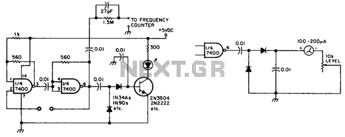
This circuit checks a crystal for activity. Two sections of a 7400 IC act as an oscillator, and its output is rectified to drive an NPN transistor that switches an LED. In an alternative configuration, a meter replaces the...