
plant soil moisture tester circuit

The soil moisture detection circuit consists of the following components: a moisture sensor, a potentiometer (R2), an LED, and a resistor. The moisture sensor is typically a pair of conductive electrodes that are inserted into the soil. When the soil is moist, the conductivity between the electrodes increases, allowing current to flow through the circuit.
The potentiometer R2 serves as a variable resistor that adjusts the sensitivity of the moisture sensor. By changing the resistance value, the user can set the moisture level at which the LED will illuminate. This feature provides flexibility, enabling the circuit to cater to different types of plants with varying moisture requirements.
The LED acts as a visual indicator; it will light up when the moisture level exceeds the set threshold. This simple yet effective design allows for easy monitoring of soil moisture, helping to prevent overwatering or underwatering of plants. The entire circuit can be powered by a 3-volt battery, ensuring portability and ease of use in various gardening applications.
Overall, this soil moisture circuit is an excellent tool for gardening enthusiasts, combining simplicity, functionality, and efficiency in plant care.A very simple and useful project of soil moisture circuit. The circuit is using only four components and a 3 volt battery. The circuit will detect if there is water in the soil of any plant and light up the LED. The resistor R2 is a potentiometer to adjust the level on which you want to make the LED on. 🔗 External reference
Related Circuits
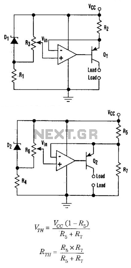
This setup can function as a cost-effective current source with an output accuracy of 1%. However, the voltage offset can activate the current source even when Vqq equals Vin. Modifying the configuration of Figure 1 can resolve the issue...
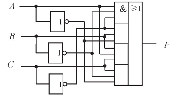
The design of the combinational logic circuit is diverse. An example chosen for detailed explanation is the implementation of an even parity check circuit. The parity check circuit exhibits particular characteristics and practicality in the analysis and design of...
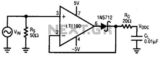
This closed-loop peak detector circuit utilizes a Schottky diode within the feedback loop to achieve high accuracy. The 20-ohm resistance RQ serves to isolate the 0.01-ohm load and prevent oscillations. The direct current (DC) value is measured using a...

NOR gates A and B create a low-frequency oscillator that activates when the CDS cell, in dark conditions, presents a logic zero to one input of NOR gate A. This low-frequency oscillator, operating at 10 Hz, enables a high-frequency...

A simple dimmer circuit can be constructed using the CMOS ICs TT8486A and TT6061A, allowing control over the intensity of an incandescent lamp through a touch contact. This electronic touch dimmer can increase the brightness of incandescent lamps in...
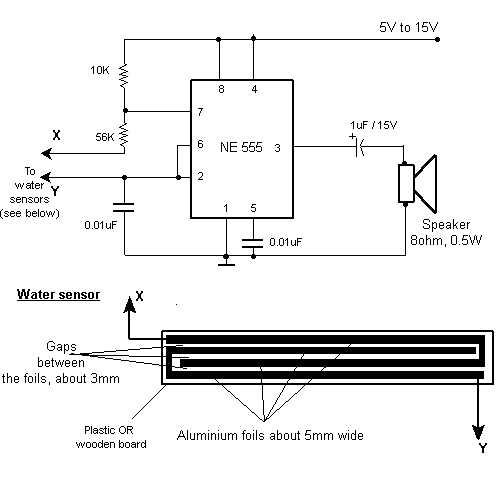
This weblog discusses electronic circuit schematics, PCB design, DIY kits, and electronic project diagrams. The rain detector operates on the principle of an astable multivibrator using the 555 timer IC, which is equipped with a sensor capable of detecting...