
Phone line Audio Visual Ringer

The circuit described functions as an auxiliary telephone ringer, allowing users to be alerted to incoming calls from a remote location. The design incorporates a simple parallel connection to existing telephone lines, utilizing twin flexible wires to integrate seamlessly without the need for an external power source.
The visual indication of an incoming call is achieved through a combination of resistor R1, diodes D5, and LED1, which illuminate when the telephone rings. The core of the audio alert system is centered around the integrated circuit IC1, either the BA8204 or ML8204, which is specifically designed for generating bell sounds in telecommunication applications. This IC is housed in an 8-pin mini DIP package, making it compact and easy to handle.
Resistor R3 is critical for adjusting the sensitivity of the bell, allowing customization based on user preference or environmental factors. The tone of the bell is controlled by resistor R5 and capacitor C4, which determine the frequency output, while resistor R4 and capacitor C3 manage the repeat frequency of the ringing sound. This flexibility enables users to experiment with different component values to achieve a tone that is most pleasing or suitable for their environment.
The operational principle of the circuit is straightforward. An incoming bell signal, typically around 75V AC, is routed through capacitor C1 and resistor R2, which then feeds into a diode bridge formed by diodes D1 through D4. This arrangement rectifies the AC signal into a DC output, which is subsequently smoothed by capacitor C2 to ensure stable operation.
The dual-tone ring signal is produced at pin 8 of the IC1, with the volume of the output sound being adjustable via a variable resistor (VR1). The final audio signal is delivered to a piezo-ceramic sound generator, which converts the electrical signal into audible sound, alerting users to incoming calls effectively. This circuit design combines simplicity and functionality, making it an ideal solution for enhancing telephone alert systems in various settings.Many a times one needs an ex- tra telephone ringer in an ad- joining room to know if there is an incoming call. For example, if the telephone is installed in the drawing room you may need an extra ringer in the bedroom.
All that needs to be done is to connect the given circuit in parallel with the existing telephone lines using twin flexible wires. This circuit does not require any external power source for its operation. The section comprising resistor R1 and diodes D5 and LED1 provides a visual indication of the ring. Remaining part of the circuit is the audio ringer based on IC1 (BA8204 or ML8204). This integrated circuit, specially designed for telec- om application as bell sound generator, requires very few external parts.
It is readily available in 8-pin mini DIP pack. Resistor R3 is used for bell sensitivity adjustment. The bell frequency is controlled by resistor R5 and capacitor C4, and the repeat frequency is controlled by resistor R4 and capacitor C3. A little experimentation with the various values of the resistors and capacitors may be carried out to obtain desired pleasing tone.
Working of the circuit is quite simple. The bell signal, approximately 75V AC, passes through capacitor C1 and resistor R2 and appears across the diode bridge comprising diodes D1 to D4. The rectified DC output is smoothed by capacitor C2. The dual-tone ring signal is output from pin 8 of IC1 and its volume is adjusted by volume control VR1.
Thereafter, it is impressed on the piezo-ceramic sound generator. 🔗 External reference
Related Circuits
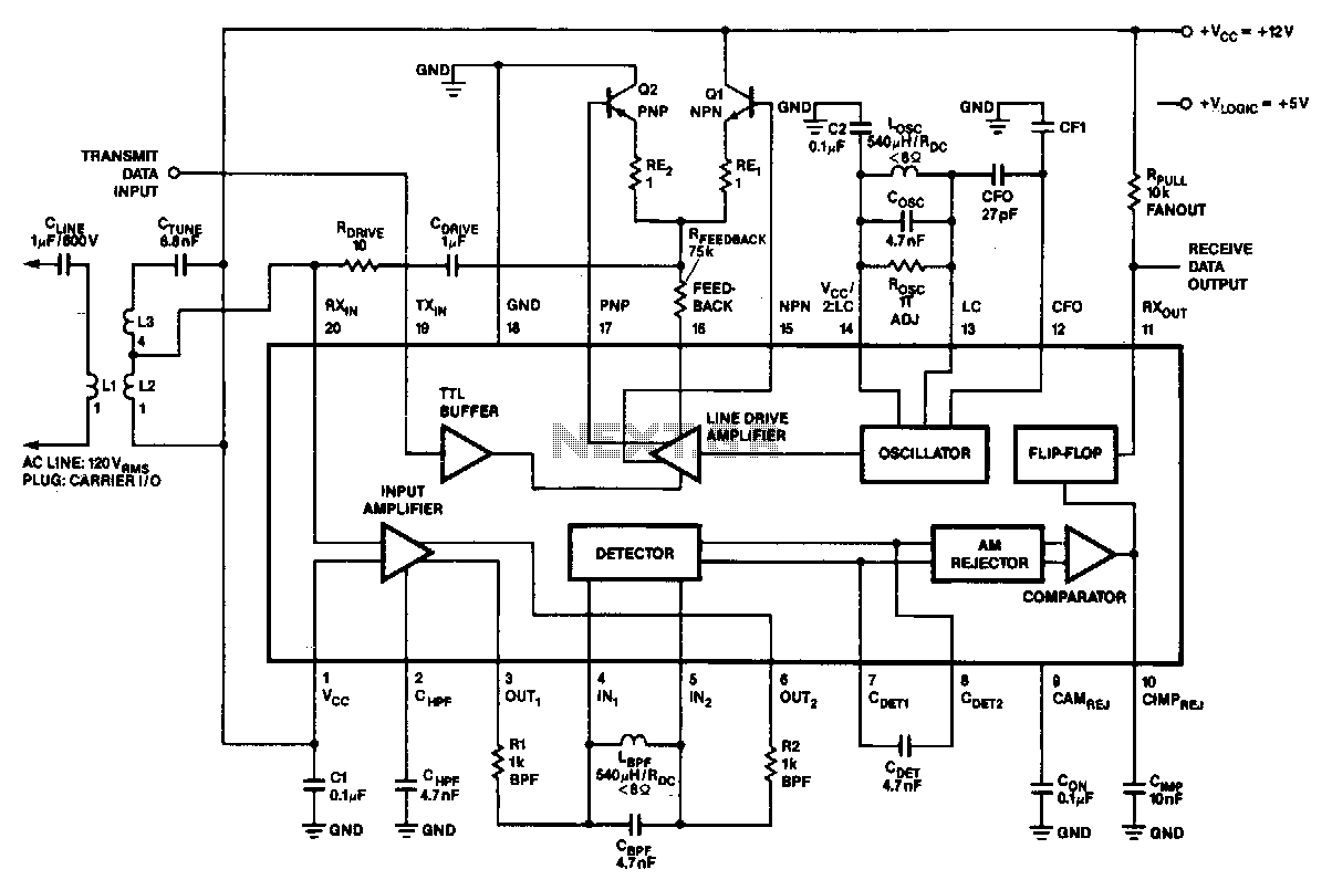
In the 100-kHz application, the coupling network feeds into the receiver section located at the bottom of the chip. The external components are summarized later. The receive data output is pulled up via a resistor (RPuLL) of approximately 10...
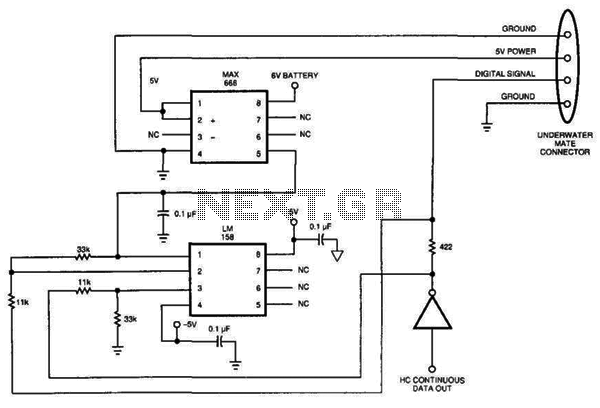
Sensing short circuits in equipment that operates underwater is particularly important. The wet-mat connector design shown in Figure 20-4 is also suitable for other remote short-circuit sensing applications. Due to the limitations imposed by the battery and voltage levels,...
TL072 is a low-noise JFET input operational amplifier characterized by features such as a common-mode input voltage range, high slew rate, operation without latch-up, compensated internal frequency, high input impedance at the JFET input stage, low noise, low total...
Any ideas? Is this circuit going to be standalone? Is there any other circuitry around it, perhaps a microcontroller? What circuitry does the timing device contain, or does it even contain electronics? Abdullah Kahraman Mar 22, '13 at 18:10....
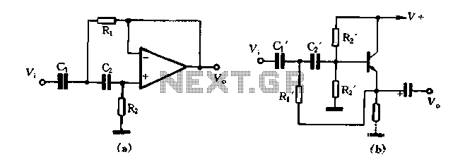
Figure 1-102 illustrates a high-pass filter in part (A). If C1 and C2 are taken as equal and R1 is set to 1/2, then the crossover frequency is given by fH = 1/(2√(2R1C1)). In part (B), if C1 and...
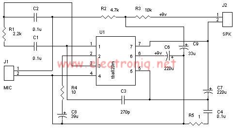
A very simple audio amplifier circuit can be designed using the TBA820M audio amplifier integrated circuit with just a few electronic components. This audio amplifier project features a high gain that allows for the detection of sounds underwater. The...