
MC34017A Telephone Tone Ringer Bipolar Linear/I2L

The MC44608 GreenLine Power Supply controller is a versatile component that can be adapted for low-power applications with careful design considerations. In the typical configuration, the controller effectively manages power output while minimizing energy waste during standby mode. To achieve further reductions in power consumption, the circuit can be modified to include a separate low-output power supply. This additional power supply should be designed to deliver less than 1.0 W, specifically tailored to meet the needs of the microprocessor.
Key components to consider for this modification include a low-dropout regulator (LDO) or a buck converter that can efficiently step down the voltage to the required levels for the microprocessor. The selection of these components is critical in maintaining efficiency and ensuring that the overall power consumption remains within the desired limits.
In addition, it is essential to include control circuitry that can effectively manage the power states of the microprocessor and the other components of the application. This may involve using a microcontroller or a dedicated power management IC that can switch off non-essential parts of the circuit during standby, thereby conserving energy.
The schematic should incorporate feedback mechanisms to monitor power levels and ensure that the microprocessor receives stable power without fluctuations that could affect performance. Proper decoupling capacitors should also be placed near the power supply pins of the microprocessor to filter out noise and maintain stable operation.
By implementing these strategies and utilizing the MC44608 in conjunction with a dedicated low-output power supply, it is feasible to achieve standby power consumption as low as 200 mW, aligning with stringent power-saving regulations while maintaining the functionality of essential components.As it is well known, according to power saving regulations, we need to obtain a very low power consumption during standby condition for all equipment continuously powered on the mains. For not saving version of power supply, the standby power consumption is around 9. 0 W (for 100 W power output). When using the MC44608 GreenLine ›› Power supply controller, we obtain 1. 3 W in standby mode. The result is absolutely phenomenal, but still, for some special applications, the power reduction is not enough. In this case the only possibility to obtain a lower consumption in standby is to use a separate low output power supply (< 1.
0 W) for powering only the Microprocessor and Switch off the rest of the application. The MC44608 is basically not designed for that use. However this is achievable by adding a few more components to the typical application schematic. In this case we CAN reach a standby power consumption as low as 200 mW. 🔗 External reference
Related Circuits
This circuit illustrates a remote control system utilizing a radio telephone circuit diagram. Features include the ability to switch appliances from any distance, overcoming various limitations. The remote control circuit employs radio frequency (RF) technology to facilitate wireless communication between...
A tone control circuit is an electronic circuit designed to manipulate the tone of an audio signal. The tone of an audio signal is analogous to color in light. The tone control circuit typically consists of various components such as...
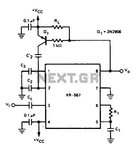
For certain applications, it is crucial to utilize a tone decoder that features a narrow bandwidth and a fast response time. This objective can be achieved with the dual time constant tone decoder circuit presented. The circuit incorporates two...
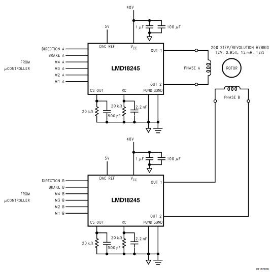
LMD18245 bipolar stepper motor driver circuit design using few electronic parts The LMD18245 is a versatile bipolar stepper motor driver designed to control stepper motors with precision and efficiency. This circuit utilizes a minimal number of electronic components, making it...
Square wave tone bursts are generated by pressing the pushbutton. The duration of these bursts is determined by how long the voltage at Pin 4 exceeds a specified threshold. The circuit described involves a square wave generator that produces tone...
Typically, a single telephone is connected to a telephone line. If an additional telephone is needed at a distance, a parallel line is installed for connecting the second telephone. This straightforward parallel line arrangement presents issues such as loss...