
I2C Interfacing Acceleration Sensing PCF8591

The LIS3L02AS4 accelerometer is a highly integrated device designed for low power consumption and high performance, making it suitable for various applications, including robotics and mobile devices. The accelerometer's three-axis measurement capability allows for comprehensive motion detection, essential for applications requiring precise orientation and movement tracking. The choice of operating voltage (2.4V to 3.6V) enables compatibility with various microcontrollers and systems, ensuring flexibility in design.
In practical applications, the outputs from the accelerometer can be processed by a microcontroller equipped with an analog-to-digital converter (ADC). The ADC converts the analog voltage levels from the accelerometer into digital values, which can then be utilized in software algorithms to interpret motion data. Depending on the configuration, the microcontroller can switch between the ±2g and ±6g sensitivity settings, allowing for adaptability based on the specific requirements of the application.
The integration of the accelerometer into an I2C bus system facilitates communication with multiple sensors and devices, enhancing the overall functionality of the robotic system. The I2C protocol supports multiple devices on a single bus, enabling efficient data exchange and reducing the complexity of wiring. This capability is particularly advantageous in applications where space and weight are critical factors.
Overall, the LIS3L02AS4 accelerometer serves as a versatile and powerful component in motion-sensing applications, providing valuable data that can enhance the performance and capabilities of robotic systems and other electronic devices.This part of the I2C interfacing project focuses on building an acceleration sensor, but in the process it also explores two other issues: advanced use of the PCF8591 chip (that we have already seen in the pressure sensor) and running the bus at 3. 3v. For the rest of myI2C series, see the table of contents. This project really shows the power of t he I2C bus in the NXT. Sensors that report a single analog value, such as temperature or pressure, can be built as analog sensors, just like the NXT`s sound and light sensors. But for an acceleration sensor that must report two or three values, the acceleration along two or three axes, anI 2C sensor is the only reasonable solution.
Acceleration sensors are wonderfully useful. They can detect that a robot bumped into a wall, they can detect that it is in a free fall (open that parachute!), they can be used to estimate position and to count steps, and much more. They are so useful that it makes you wonder why Lego did not include one inside the NXT. There are two commercial acceleration sensors for the NXT, one from HiTechnic and several from Mindsensors.
The sensor that I am describing here is better than all of these in some ways (it can be configured by your program to two sensitivities unlike all the commercial sensors that have a fixed sensitivity, and it measures acceleration along 3 axes, whereas some of the commercial ones are 2-axis sensors). But the commercial ones have higher resolution, and of course, you don`t have to build them yourself.
The sensor uses an accelerometer called LIS3L02AS4, manufactured by STMicroelectronics. This device is a single silicon chip that contains sensing elements that can measure accelerateion in three directions and some analog electronics that make it easy to use the chip (amplfiers, multiplexers, and so on). The chip needs a supply of 2. 4 to 3. 6v. It has three analog outputs. The voltage in each output is proportional to the acceleration in one particular direction (X, Y, or Z).
The sensitivity of the outputs can be set so that the chip measures acceleration either in the range ±2g (g is the unit of acceleration, about 9. 8m ·s ’2) or in the range ±6g. When there is no acceleration in a given axis, the output voltage is half the supply voltage (Vdd). When the sensor is subject to acceleration or deceleration, the voltage changes by Vdd/5 volts/gin the ±2g scale or byVdd/15 volts/gin the ±6g scale.
This means that if the supply voltage is 3. 3v, the outputs range from 0. 33v to 2. 97v. These are nominal values; the actual sensitivity can differ by up to 10% or so. You use such a sensor by connecting its outputs to analog-to-digital converters, to obtain digital measurements. The scale is set to ±2g or ±6g by connecting one of the pins to either ground or Vdd. In a device that always use one of the scales, you can connect this pin permanently to the ground or to the supply line.
If you want to configure the sensitivity at run time, you can connect this pin to a voltage that you can control from the program. How does this sensor (and similar like it) work The principle is fairly simple. Think of a mass that is suspended between two springs that are both at rest, and which can only move left and right, as shown in the diagram on the right.
If the whole structure is moving, say to the left, at a constant speed, the two springs will remain at rest and the mass will remain exactly in the middle between the two walls. If the structure is now accelerating (to the left), the inertia of the mass will cause it to continue to travel at a constant speed, which will cause the left spring to compress and the right one to extend a bit.
The compression/extension of the springs excerts elastic force to be applied to the mass. If the structure starts moving at a constant speed again, this elastic force will eventually return the mass to the center of the structure. Silicon accelerometers (often c 🔗 External reference
Related Circuits
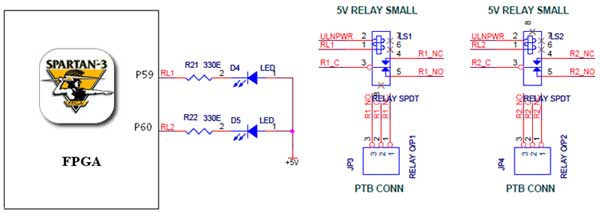
The Spartan-3 board features external 5V relay interfacing, as depicted in the accompanying figure. The ULN2803 is utilized as a driver for the FPGA I/O lines, with the driver outputs connected to the relay modules. A PTB connector is...
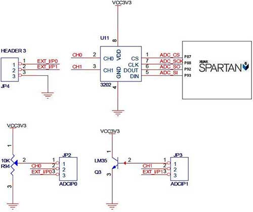
The Spartan-6 board features a 2-channel, 12-bit SPI ADC, as shown in the accompanying figure. In synchronous serial communication, a clock line (SCK in the case of SPI) is used to synchronize data transfer, with the clock being controlled...
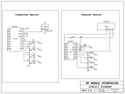
This document presents a circuit example for interfacing an RF module using the HT12E/D encoder-decoder pair. The attached circuit can be utilized for data transmission via the RF module, which is designed for single-channel operation, allowing only serial data...
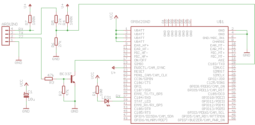
The Arduino can communicate over various networks, including Ethernet, Bluetooth, Wi-Fi, XBEE, and GPRS. A Telit GM862-GPS module, which has GPRS and GPS capabilities accessible via AT commands, has been repurposed for use with the Arduino. The GM862's logic...
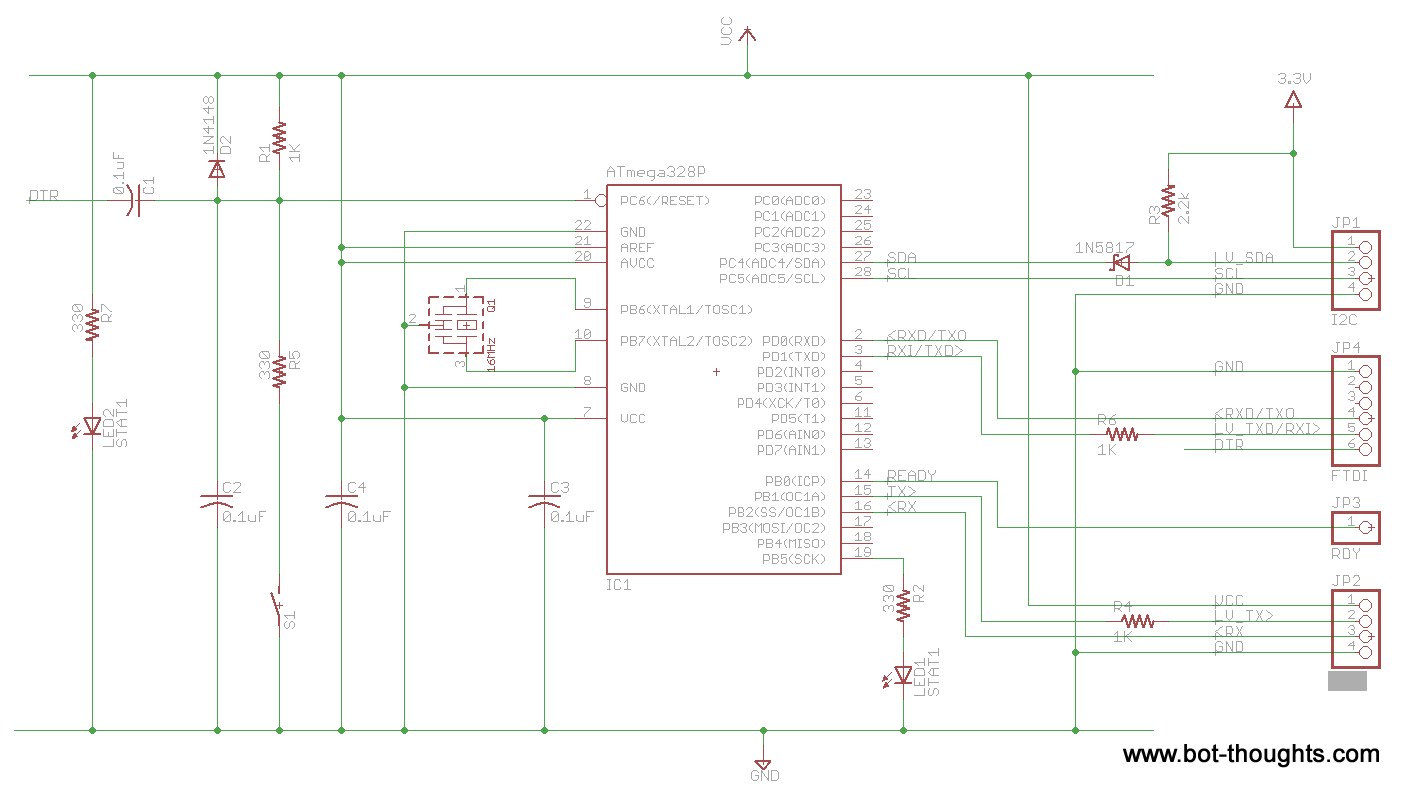
This is a slight redesign of a previously created board intended for an undisclosed purpose. It is an Arduino clone that communicates serially on one set of pins using NewSoftSerial and utilizes I2C on the standard pins. The board...
I2C, pronounced "I squared C," stands for Inter-Integrated Circuit. This protocol was developed by Philips Semiconductors around 1992 to facilitate easy communication between components on the same circuit board, achieving transfer rates of up to 400 kbit/sec. It utilizes...