
relay interfacing with spartan 3 primer

The Spartan-3 board is designed to facilitate the integration of relay modules, enabling control of higher voltage and current loads through the FPGA. The ULN2803 is a high-voltage, high-current Darlington transistor array, which effectively drives the relays by providing sufficient current and voltage levels from the FPGA's I/O lines. The use of this driver ensures that the FPGA remains protected from the electrical demands of the relay coils.
The relay modules connected to the ULN2803 can switch various devices, such as motors, lamps, or other electrical appliances, making the Spartan-3 board suitable for applications in automation, robotics, and control systems. The PTB connector allows for an external power supply, ensuring that the relays can operate independently of the FPGA’s power source, thereby enhancing system stability and reliability.
In schematic representation, the ULN2803 would be connected to the FPGA I/O pins, with each output of the ULN2803 linked to the control terminals of the respective relay module. The relay modules would then be connected to their respective loads, with appropriate flyback diodes included across the relay coils to prevent back EMF from damaging the ULN2803 or the FPGA. The PTB connector would be wired to supply the necessary 5V to the relay modules, ensuring that the entire system can operate efficiently under varying load conditions.
Overall, this configuration allows for effective control over multiple relays, broadening the functionality of the Spartan-3 board in various electronic and robotic applications.The Spartan-3 board has external 5v Relay interfacing, indicated as in Figure. ULN2803 is used as a driver for FPGA I/O lines, drivers output connected to relay modules. PTB connector provided for external power supply if needed. 🔗 External reference
Related Circuits
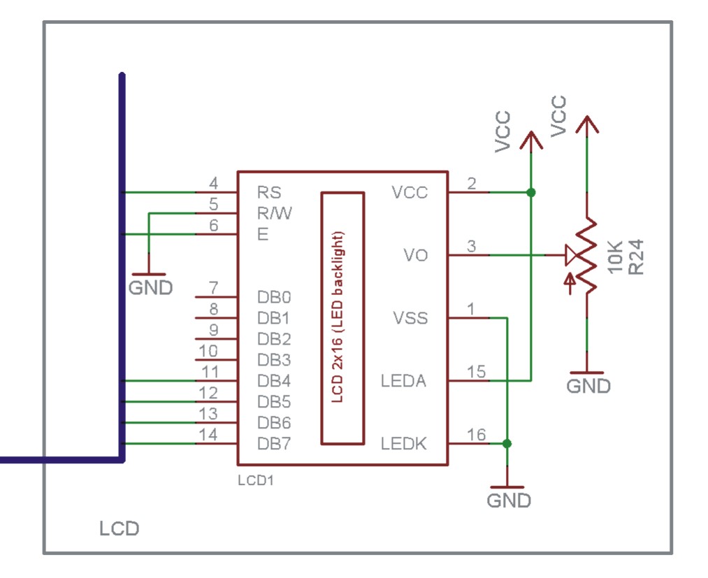
The EN line is referred to as 'Enable'. This control line is utilized to indicate to the LCD that data is being sent. To transmit data to the LCD, the program must ensure that this line is low (0),...
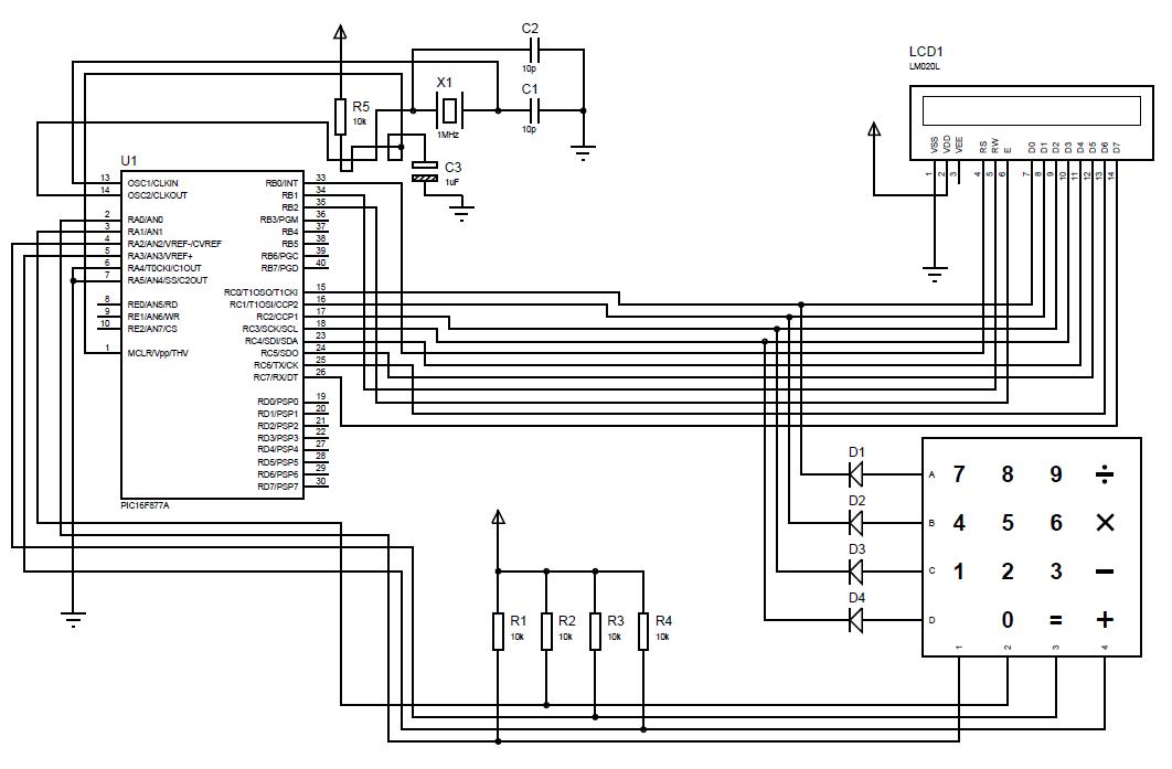
A beginner or hobbyist is seeking to learn more about microcontrollers. The objective is to display an output on an LCD when a button on the keypad is pressed. To achieve the desired functionality of displaying output on an LCD...
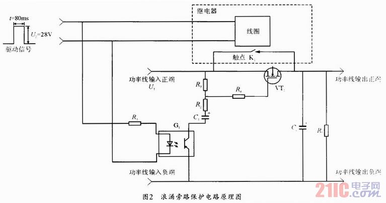
During the power-up of the apparatus, the capacitor is primarily responsible for the emergence of surge current. The schematic diagram of the principle is illustrated in Fig. 1. After K1 closes, the capacitor begins to charge, assuming that the...
This is a simple circuit which I built to one of my audio amplifier projects to control the speaker output relay. The purpose of this circuit is to control the relay which turns on the speaker output relay in...
Some relays will become warm if they remain energized for some time. The circuit shown here will actuate the relay as before but then reduce the hold current through the relay coil by about 50%, thus considerably reducing the...
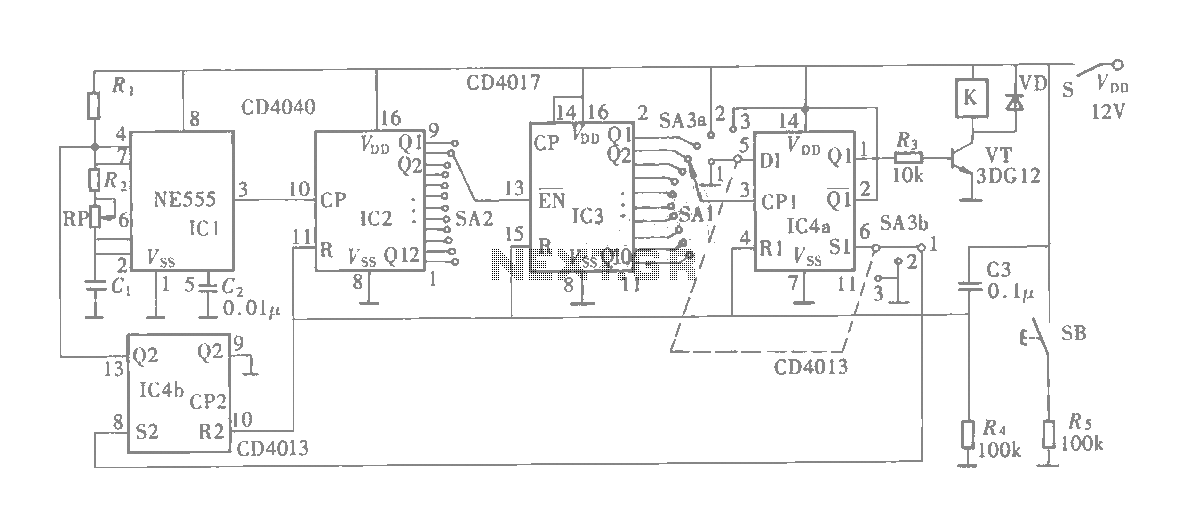
The multifunction circuit primarily refers to its capability to operate in three modes: "delayed pull," "time release," and "delayed cycle." The term "delay" indicates that the relay is energized after a predetermined time; however, the relay does not activate...