
Electronic Door Release

This circuit operates by integrating a keypad input system with a relay control mechanism, allowing for secure access control applications such as door release systems. The four-digit code entry mechanism is pivotal, wherein each key corresponds to specific terminals that interface with the control logic. The relay serves as the output actuator, capable of energizing various devices, including door strikes or electronic locks, based on the input code.
The design is flexible, allowing the use of different relay types depending on the voltage requirements of the application. The circuit's adaptability is further enhanced by the ability to modify the timing of the relay's activation and deactivation through the selection of C4 and R4 values. The inclusion of a transistor (Q2) for error detection ensures that any incorrect key presses or out-of-sequence entries will result in immediate feedback, preventing unauthorized access.
The circuit board layout must be carefully designed to ensure that low-voltage components are adequately isolated from relay contacts, especially when high-voltage switching is involved. This is critical for maintaining safety and preventing damage to sensitive components. The use of a keypad with a common terminal facilitates straightforward wiring and simplifies the code entry process, while the additional incorrect keys allow for more complex and secure code configurations.
Overall, this circuit presents a robust solution for electrical access control, combining user-friendly code entry with reliable relay operation, suitable for various applications beyond just door release mechanisms.This circuit is designed to operate an electrical door-release mechanism - but it will have other applications. Enter the four-digit code of your choice - and the relay will energize for the period of time set by C4 & R4.
Use the relay contacts to power the release mechanism. The standby current is virtually zero - so battery power is a realistic option. The circuit is drawn with a 12-volt supply - but it will work at anything from 5 to 15-volts. All you have to do is choose a relay suitable for the supply voltage you want to use. Replace the SPCO/SPDT relay with a multi-pole relay - if it suits your application. Do not use the "on-board" relay to switch mains voltage. The board`s layout does not offer sufficient isolation between the relay contacts and the low-voltage components. If you want to switch mains voltage - mount a suitably rated relay somewhere safe - Away From The Board.
Choose the four keys you want to use as your code - and connect them to "A B C & D". Wire the common to R1 and all the remaining keys to "E". When you press your four keys - in the right order - the relay will energize. With the values of C4 & R4 as shown - and with R4 set to its maximum - the relay will de-energized about one minute after "D" is released. However - if you replace C4 with a 100nF capacitor - and replace R4 with a 4k7 fixed resistor - the relay will de-energize the moment "D" is released.
Any keys not wired to "A B C & D" are connected to the base of Q2. Whenever one of these "Wrong" keys is pressed - Q2 takes pin 1 low and the code entry fails. Similarly, if "C" or "D" is pressed out of sequence - Q4 or Q3 will take pin 1 low and the code entry will fail. If you make a mistake while entering the code - simply start again. The Keypad must be the kind with a common terminal and a separate connection for each key. On a 12-key pad, look for 13 terminals. The matrix type with 7 or 8 terminals will NOT do. A 12-key pad has eight "Wrong" keys connected to "E". If you need a more secure code - use a bigger keypad with more "Wrong" keys. The Support Material for this circuit includes a step-by-step guide to the construction of the circuit board, a parts list, a detailed circuit description and more.
🔗 External reference
Related Circuits
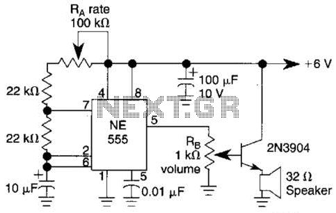
Ra sets the rate while RH sets the volume of clocks in the speaker. The 555 is configured as a low frequency oscillator. The circuit is powered by a 6 V battery. The circuit utilizes a 555 timer IC configured...
While it may lack the aesthetic appeal of traditional mercury barometers featuring elongated glass tubes mounted on intricately carved wooden bases, the Torricelli barometer described here serves as a functional equivalent and electronic replica of the original Torricelli barometer....
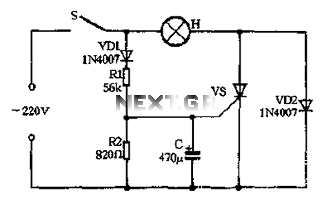
The circuit operates as follows: When the momentary switch S is activated, the voltage across the capacitor cannot change instantly, resulting in zero voltage across the SCR, which does not trigger. Consequently, the voltage cut-off occurs. In this scenario,...

A simple FM transmitter circuit can be designed using the MC2833 integrated circuit, which is intended for cordless telephone and FM communication applications. This circuit includes a microphone amplifier, a voltage-controlled oscillator, and two auxiliary transistors. The final output...

Transistors Q1 and Q2 control latches Q3 and Q4 to switch on the lamp. A high resistance from touching the electrode biases Q1 or Q2 on, setting or resetting the latch. In this circuit, transistors Q1 and Q2 function as...
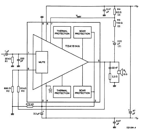
The TDA1514 audio amplifier circuit design is an electronic project capable of delivering high audio power output using a specialized audio integrated circuit (IC) and a few common components. Manufactured by Philips Semiconductor, the TDA1514 audio IC can provide...