
IC 4049 Square wave oscillator generator

The CD4049 is a hex inverting buffer, which means it contains six independent inverters that can be used to generate square wave signals. This IC operates on a wide voltage range, typically from 3V to 15V, making it versatile for various applications. The primary function of the CD4049 in the square wave oscillator circuit is to invert the input signal, allowing for the generation of a square wave output.
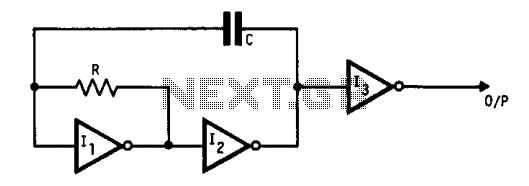
To design a square wave oscillator using the CD4049, a common approach is to implement a feedback configuration with external resistors and capacitors. The basic circuit consists of connecting one of the inverters in a feedback loop with a resistor (R) and a capacitor (C) connected to the input and output terminals. The values of R and C will determine the frequency of the oscillation, which can be calculated using the formula:
\[ f = \frac{1}{2 \pi R C} \]
where \( f \) is the frequency of the square wave.
The output waveform will alternate between high and low states, creating a square wave signal. The duty cycle of the output can also be adjusted by selecting appropriate resistor and capacitor values. In addition, the CD4049 can drive loads directly, making it suitable for interfacing with other digital circuits or components.
When designing the circuit, it is important to consider power supply decoupling to ensure stable operation, as well as the input and output characteristics of the IC to prevent distortion of the generated waveform. Proper layout and grounding techniques should also be employed to minimize noise and ensure reliable performance.
Overall, the CD4049 Hex Inverting Buffer IC is an effective component for creating square wave oscillators, providing flexibility and ease of implementation in various electronic applications.We can bring the inverter CMOS digital IC is CD4049 Hex Inverting Buffer IC, to design the Square wave oscillator generator.. 🔗 External reference
Related Circuits
This oscillator utilizes standard inverters, one resistor, and one capacitor, and it does not have a minimum operating frequency. The resistor (R) and capacitor (C) must be selected to ensure that the currents flowing into the gates remain below...
This is a sine wave oscillator circuit, also known as an amplitude-stabilized sine-wave oscillator. It provides a high-purity sine wave output. This sine wave oscillator circuit is designed to generate a stable sine wave output with minimal distortion, making it...
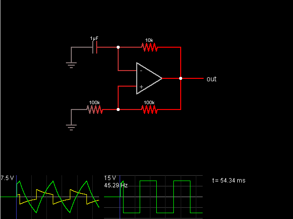
This circuit is an oscillator that generates a square wave. The operational amplifier (op-amp) begins with its two inputs in an undefined state, starting with the non-inverting input slightly higher than the inverting input. The op-amp significantly amplifies this...
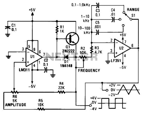
This is a simple triangle-wave generator utilizing two integrated circuit (IC) devices and a transistor. The triangle wave serves as feedback to the square-wave generator. It allows range switching across three intervals from 100 Hz to 100 kHz. Additional...
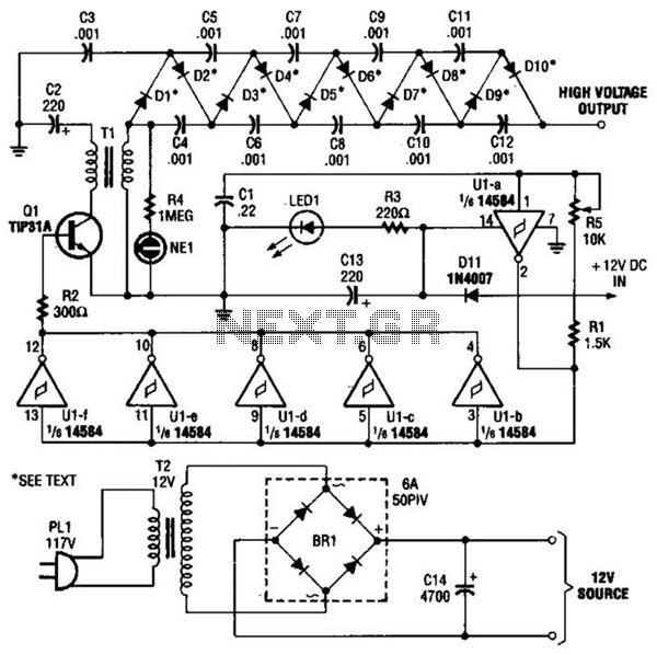
In the miniature high-voltage DC generator, the circuit receives input from a 12 V DC power supply, which is amplified to produce a 10,000 V DC output. This process induces a pulsating signal of opposite polarity in the secondary...
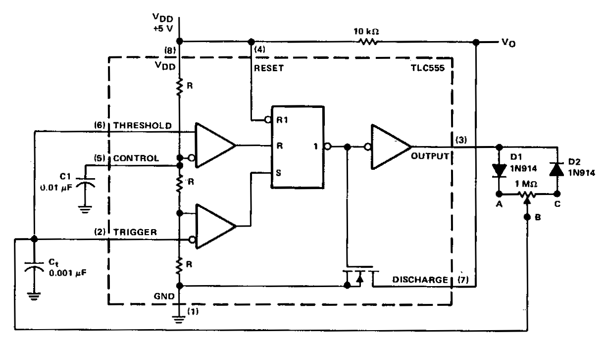
In a basic astable timer, the timing periods 11 and 12 are not independently controlled. This lack of control complicates the maintenance of a constant period, T, if either 11 or 12 is varied. In this circuit, the charge...