
Relaxation Oscillator

The described oscillator circuit utilizes an operational amplifier configured in a feedback loop to produce a square wave output. The circuit operates by exploiting the characteristics of the op-amp and the charging and discharging behavior of the capacitor. Initially, when the output is at 15 V, the voltage divider formed by the two 100k resistors sets the non-inverting input to 7.5 V. The inverting input, being grounded, ensures that the op-amp remains in a high state.
As the capacitor charges through the op-amp's output, it accumulates voltage until it reaches a threshold slightly above 7.5 V. At this point, the op-amp's output transitions from 15 V to -15 V, effectively flipping the output state and causing the non-inverting input to drop to -7.5 V. This rapid change in output voltage creates the square wave characteristic of the oscillator.
The frequency of oscillation can be adjusted by varying the capacitance of the capacitor or the resistance values of the resistors in the feedback loop. The design allows for a stable oscillation as long as the op-amp operates within its specified voltage and current limits. This oscillator circuit can be utilized in various applications, such as clock generation for digital circuits, tone generation in audio applications, or as a basic signal generator in testing scenarios. Proper consideration of component tolerances and power supply stability is essential for reliable operation.This circuit is an oscillator that generates a square wave. The op-amp starts with its two inputs in an unknown state; let`s say it starts with + slightly higher than. The op-amp greatly amplifies this difference, bringing its output to the op-amp`s positive power supply voltage, its maximum output (15 V in this case).
The two 100k resistors a ct as a voltage divider which put the + input at half the output voltage, or 7. 5 V. The input is at ground, lower than the + input, so the op-amp output stays at 15 V. Current flows from the op-amp output to ground through the capacitor, charging it. As soon as it charges to slightly more than 7. 5 V, the input is now higher than the +, and so the output flips to -15 V. This brings the + input to -7. 5 V. 🔗 External reference
Related Circuits
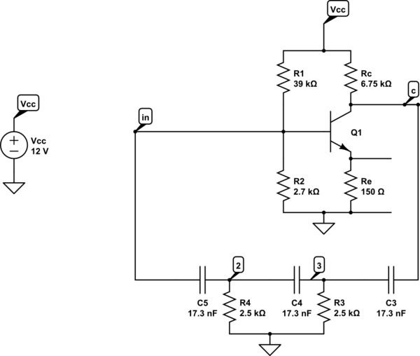
A phase shift oscillator utilizing a common emitter (CE) amplifier. The circuit operates with a collector voltage (Vc) of approximately 6V and achieves a gain of around 40, exceeding the minimum requirement of 29. The target oscillation frequency is...
The figure illustrates a multiple output crystal oscillator, which primarily consists of three gates of Al, four resistors, two capacitors, and a crystal. Resistors R1 to R4 offset two inverters within the linear range and are connected between pin...
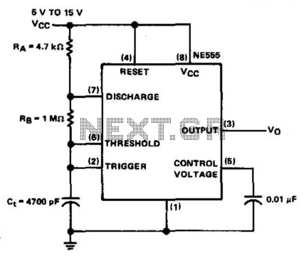
The NE555 timer is configured in astable mode and utilizes three timing components (RA, RB, and Ct). A 0.01 µF bypass capacitor is connected to pin 5 to enhance noise immunity. The operational limitations of the astable mode are...
The schematic below illustrates the division of a crystal oscillator signal by the crystal frequency to obtain an accurate 1-second time base with a precision of 0.01%. Two cascaded 12-stage counters (CD4040) form a 24-stage binary counter, and the...
A tutorial on the Wien Bridge Oscillator circuit, which utilizes an RC phase shift oscillator to generate sine waves. The Wien Bridge Oscillator is a well-known electronic circuit used to produce sine waves. It operates based on the principle of...
This voltage-controlled oscillator circuit is compact and exhibits good linearity. The precision can be better than 0.01% if properly constructed. The circuit provides three different output waveforms: square, triangle, and sawtooth, which are essential for music synthesizers and measurement...