
IC 555 Light Alarm

The IC 555 timer is a versatile integrated circuit widely used in various timer, delay, pulse generation, and oscillator applications. In the context of the Light Alarm circuit, the IC 555 operates in monostable mode, where it is triggered by the detection of light levels that correspond to dawn.
The circuit typically consists of the following components: a phototransistor or light-dependent resistor (LDR) to sense ambient light, a potentiometer for adjusting sensitivity, and a speaker or buzzer for the alarm sound. When the light level rises—indicating the break of dawn—the LDR or phototransistor conducts, sending a signal to the trigger pin of the IC 555. This initiates the timing cycle, which can be adjusted using external resistors and capacitors to determine how long the alarm will sound.
The output from the IC 555 activates the speaker or buzzer, producing a loud sound designed to wake the user. The circuit can be modified by changing the component values to suit individual preferences, such as adjusting the alarm duration or sensitivity to light. Additionally, incorporating a delay feature can allow the user to set a specific time after dawn for the alarm to sound, further enhancing the circuit's functionality.
This Light Alarm circuit provides an effective solution for individuals who find it challenging to wake up in the morning, ensuring they are alerted at the appropriate time as natural light increases.IC 555, Light Alarm (Sun Up Alarm) , This circuit designed to sound a loud alarm at the break of the dawn especially for those wh cannot wake up even with an alarm clock. Circuit can be modifi.. 🔗 External reference
Related Circuits
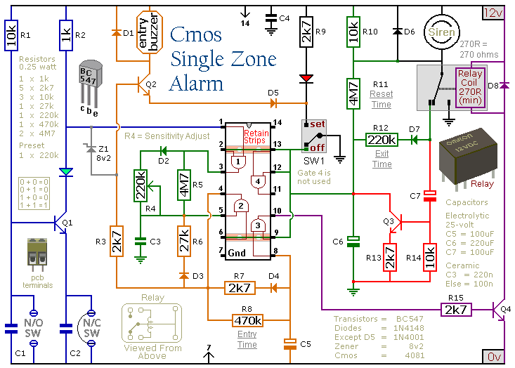
This circuit includes automatic exit and entry delays, a timed bell cut-off, and a system reset feature. It is designed to support both normally-open and normally-closed switches and can accommodate standard input devices such as pressure mats, magnetic reed...
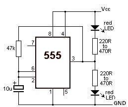
This LED flasher circuit utilizes the 555 timer integrated circuit (IC). The circuit diagram is straightforward and requires only a few external components. When operational, the red LEDs will flash sequentially at a predetermined frequency, similar to the indicators...

An electronic decorative peacock consists of 10 light-emitting diodes (LEDs), each of which contains multiple LEDs arranged in the tail of the peacock model. The light emission drive circuit operates the fan-shaped LEDs in a cyclic manner, emitting light...

The operation of the circuit is divided into three parts: low-frequency production, high-frequency manufacturing, and low-frequency extension. The low-frequency signal is generated from IC1, which is connected to an astable multivibrator circuit. The frequency is determined by the resistor...
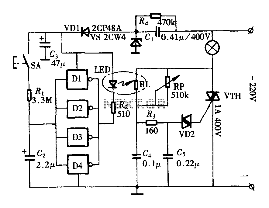
The lighting controller depicted in the figure features a gradual dimming function that prevents sudden brightness changes, which can irritate the human eye and potentially cause damage due to inrush currents. The circuit design includes a six-stage CD4069 inverter...
The report provides information related to light sensors, photoresistors, comparators, and associated circuits. It contains extensive details regarding detection. Light sensors are devices that detect and respond to light levels in the environment. A common type of light sensor is...