
ic 555 motorcycle alarm circuit

The described circuit involves a security system for motorcycles, utilizing multiple normally-open switches to enhance functionality and safety. The inclusion of tilt switches is particularly advantageous, as they serve to activate the alarm under specific conditions, such as when the motorcycle is tilted or lifted, thus preventing unauthorized use. Micro-switches add another layer of security by safeguarding access to removable panels and storage compartments, ensuring that critical components remain protected.
The alarm system operates with an extremely low standby current, which is beneficial for battery longevity, making it suitable for motorcycles that may not be used frequently. The activation mechanism of the alarm is governed by the timing components R7, R8, and C4. This configuration allows for customization of the sound duration and silent intervals, enabling users to tailor the alarm's response to their preferences. The use of an electronic siren rated for 300 to 400 mA ensures that the alarm generates a noticeable sound without overwhelming the motorcycle's electrical system.
In cases where the motorcycle horn is considered for use with the alarm, it is essential to incorporate a relay capable of handling the horn's current requirements, as the alarm's relay alone is insufficient. This relay acts as an intermediary, allowing the alarm system to control high-current devices such as the horn or lights without risking damage to the alarm circuitry.
Environmental protection is a critical aspect of the circuit design. The circuit board and switches must be adequately shielded to prevent damage from moisture and condensation, which could compromise the system's functionality. The installation of a 1-amp in-line fuse near the power source is a vital safety measure, designed to protect the wiring from potential overloads. The specific wiring and installation process will depend on the motorcycle model, which necessitates careful consideration during setup to ensure optimal performance and reliability of the alarm system.Any number of normally-open switches may be used. Fit "tilt" switches that close when the steering is moved or when the bike is lifted off its side-stand or pushed forward off its centre-stand. Use micro-switches to protect removable panels and the lids of panniers etc. The alarm`s standby current is virtually zero - so it won`t drain your battery . Once activated - the rate at which the siren switches on and off is controlled by R7, R8 & C4. For example, increasing R7 will make the sound period longer - while increasing R8 gives longer silent periods. The circuit is designed to use an electronic Siren drawing 300 to 400mA. It`s not usually a good idea to use the bike`s own Horn because it can be easily located and disconnected.
However - if you choose to use the Horn - remember that the alarm relay is too small to carry the necessary current. Connect the coil of a suitably rated relay to the "Siren" output. This can then be used to sound the Horn, flash the lights etc. The circuit board and switches must be protected from the elements. Dampness or condensation will cause malfunction. Connect a 1-amp in-line fuse AS CLOSE AS POSSIBLE to your power source. This is VERY IMPORTANT. The fuse is there to protect the wiring - not the alarm. Exactly how the system is fitted will depend on the make of your particular machine - so I`m unable to provide any further help or advice in this regard.
🔗 External reference
Related Circuits

A feedback oscillator circuit utilizing inductance is presented, featuring the 3DG3 transistor. The component parameters reference values include: 1) transistors 3DG6, 2) resistances R1 at 91 kΩ, R2 at 11 kΩ, and R3 unspecified, 3) capacitance values of C...
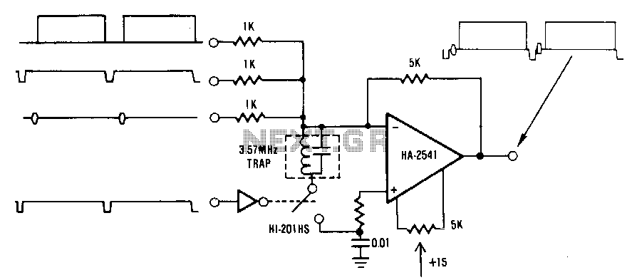
This circuit is a conventional summing amplifier configuration that incorporates a de-clamping circuit. The operation is straightforward; each component—synchronization, color burst, picture information, etc.—of the composite video signal is connected to its respective input terminal of the amplifier. These...

A simple encoder circuit for a DC motor can be constructed using the provided circuit diagram. The system includes the HA-2542 operational amplifier, a small 12 V DC motor, and a position encoder. During operation, the encoder generates a...
Operating radio transmitters without a license is illegal in most countries, so caution is advised with transmitter circuits. This FM low-power circuit is designed to operate within the 87-108 MHz band II, providing a range of approximately 20 to...

The schematic illustrates a typical application circuit for the FAN5009, a dual bootstrapped 12V high-frequency MOSFET driver. When integrated with a multi-phase PWM controller and power MOSFETs, it can form a complete core voltage regulator for microprocessors, as specified...
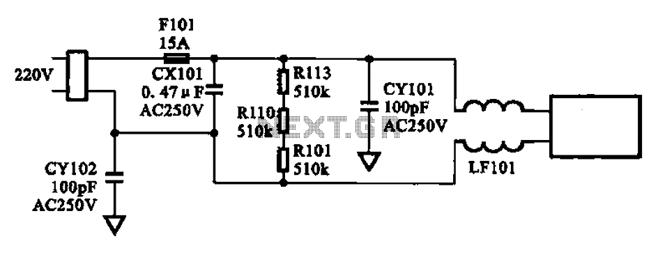
The AC input circuit consists of a fuse (Fl01), a mutual inductance filter (LF101), and filter capacitors (CX101, CY101, CY102), among other components. Its primary function is to filter out noise and pulse interference from the AC circuit, as...