
Inductance feedback oscillator circuit

The feedback oscillator circuit described operates by utilizing the properties of inductance and capacitance to generate oscillations. The circuit comprises a transistor (3DG3) that plays a critical role in amplifying the feedback signals. The resistances in the circuit, specifically R1 (91 kΩ) and R2 (11 kΩ), set the biasing conditions and influence the gain of the oscillator. The unspecified resistance R3 may be included for stability or tuning purposes.
Capacitance is provided by a capacitor (C) rated at 0.01 µF, which, together with the inductors L1 and L2, determines the resonant frequency of the oscillator. The selection of these components is crucial, as they dictate the frequency at which the circuit will oscillate. The resonant frequency (f) can be calculated using the formula:
\[ f = \frac{1}{2\pi\sqrt{L \cdot C}} \]
where L is the equivalent inductance of L1 and L2 in series or parallel, depending on their configuration, and C is the capacitance.
The AC equivalent circuit demonstrates how the capacitor and inductors form a selective circuit that allows certain frequencies to pass while attenuating others. With the transistor's emitter grounded, the circuit is configured to provide positive feedback. The output voltage (Uo) is derived from the input voltage (UI), while the feedback voltage (Uf) is taken across L2. The phase difference of 180 degrees between Uf and Uo is essential for sustaining oscillations, as it ensures that the feedback reinforces the input signal.
In summary, this feedback oscillator circuit is a classic example of utilizing transistors, resistors, capacitors, and inductors to create a stable oscillatory output. The careful selection of component values directly influences the performance and frequency of the oscillation, making it suitable for various applications in signal generation and processing.Feedback oscillator circuit inductance shown, transistor 3DG3. Component Parameters Reference values are as follows: 1) transistors 3DG6. 2) Resistance: Rhl 91kfl, RBZ llkfl, R e IkSl. 3) capacitance: C C C 0.OlyF. 4) C and LJ, L2 value is determined by the oscillation frequency. As can be seen from the AC equivalent circuit, a capacitor C and inductance L., Lz constitute a selective circuit, the transistor emitter is grounded. The output voltage Uo - UI], electrical feedback. Voltage Uf -UL2, feedback voltage Uf and the output voltage U
Related Circuits
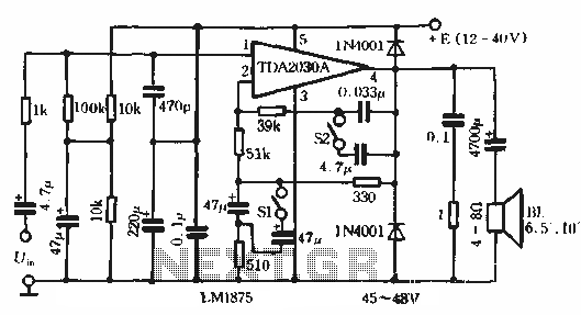
This circuit features bass boost compensation for a practical power amplifier. It is important to adhere to the specified parameters of the amplifier circuit elements. When switches S1 and S2 are disconnected, the bass boost function can be set...
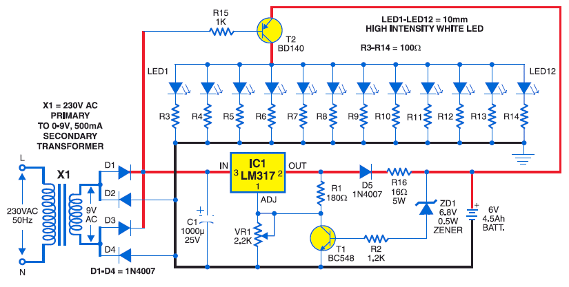
The Zener diode may not be providing sufficient current in its breakdown state to activate the transistor. Removing resistor R2 did not resolve the issue. The Zener's voltage selection could be too high, potentially preventing it from regulating the...
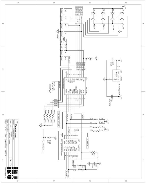
The following are detailed schematics for the QScreen Controller. The QScreen Controller integrates an embedded computer utilizing the 68HC11 microcontroller, along with a touch panel and an LCD (liquid crystal display) graphic user interface (GUI) that is well-suited for...
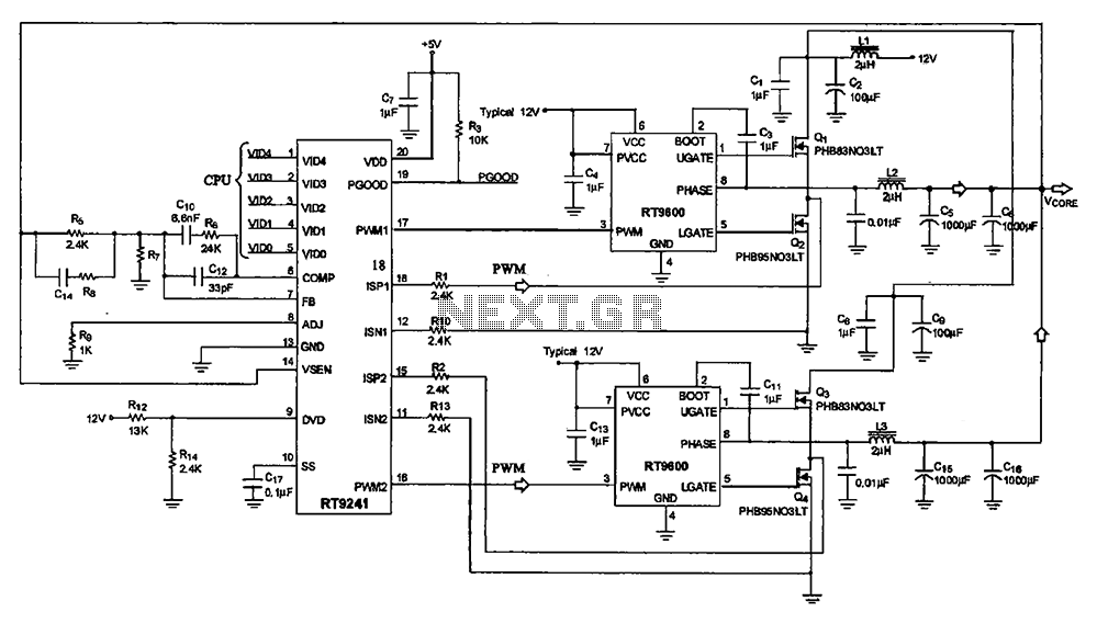
A typical computer motherboard CPU power supply circuit is primarily composed of the main power supply management chip RT9241 and additional components from the power management chip RT9600. The voltage command signal from the CPU is input into the...
This is an inexpensive DC voltage doubler circuit diagram that requires a minimal number of components and is capable of delivering 10V from a 5V power supply. If the oscillator needs to be... The circuit operates on the principle of...
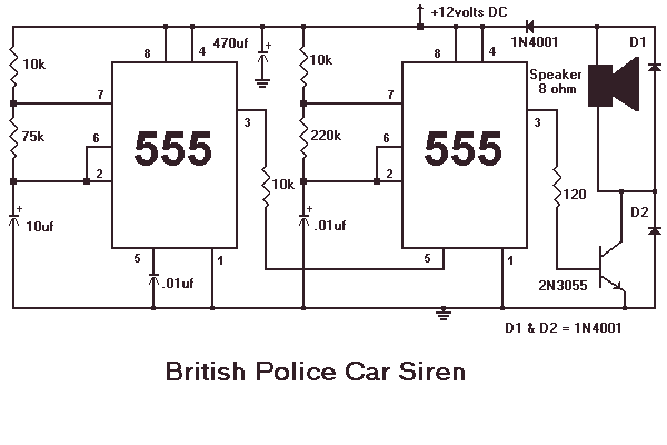
This month I am making 3 different types of siren circuits based on the 555 timer. The first circuit simulates the siren of a British police car. It uses two 555 timers in the circuit. The 555 on the...