
Stereo VU Meter

The STEREO LED LEVEL METER is designed to provide a visual representation of audio signal levels in a stereo configuration. The circuit utilizes a series of light-emitting diodes (LEDs) arranged in a bar graph format to indicate the amplitude of audio signals. The simplicity of the design allows for the use of common electronic components, making it cost-effective and accessible for hobbyists and engineers alike.
The core of the circuit consists of 22 transistors that serve as signal amplifiers and switches for the LEDs. Each transistor is responsible for controlling the activation of specific LEDs based on the input audio level. The transistors are arranged in a manner that allows for a smooth transition of LED illumination, creating a visually appealing level meter.
Resistors and diodes are incorporated into the circuit to manage current flow and protect components from voltage spikes. The use of electrolytic capacitors ensures stable power supply and signal smoothing, which is crucial for accurate level representation. The absence of integrated circuit chips, such as the LM 3914 or LM 3915, is a deliberate design choice aimed at enhancing reliability and minimizing dependency on specific components that may be less accessible.
In operation, the STEREO LED LEVEL METER receives audio signals through its input terminals. The audio signal is then processed by the transistors, which respond to the varying signal levels. As the audio level increases, more LEDs are illuminated, providing a clear and immediate visual indication of the signal strength. This feature is particularly useful in audio mixing and monitoring applications, where precise level assessment is essential.
Overall, the STEREO LED LEVEL METER stands out for its straightforward construction and effectiveness in displaying audio levels, making it an excellent project for those interested in electronics and audio technology.This is it. It`s a STEREO LED LEVEL METER. It`s the cheapest and best bar graph display available and best of all, it uses readily available components. You only need a handful of LEDs, 22 transistors, some resistors, diodes and a set of electros - it doesn`t require any chips.
You may be wondering why we didn`t choose the LM 3914 or LM 3915 bar-graph LED driver chips. The reason is simple. We learnt our lesson from our Mini Frequency Counter Book. In it we used a relatively novel chip, the CD 4026. And after releasing 10,0 🔗 External reference
Related Circuits
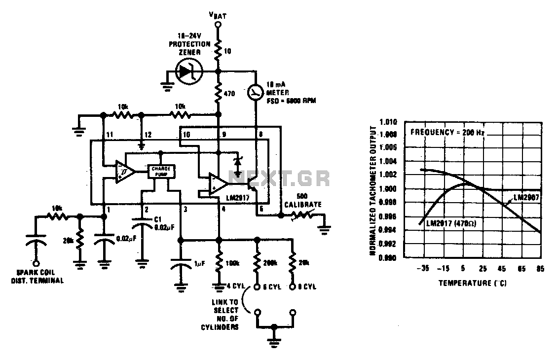
This tachometer can be configured for any number of cylinders by connecting the appropriate timing resistor as illustrated. A 500-ohm trim resistor can be utilized for final calibration. Additionally, a protection circuit consisting of a 10-ohm resistor and a...
This circuit functions similarly to the previous one and features a 4 LED bar graph that displays the voltage of a common 3.6-volt lithium-ion rechargeable cell phone battery. The reference voltage is supplied by a TL431 programmable voltage source,...
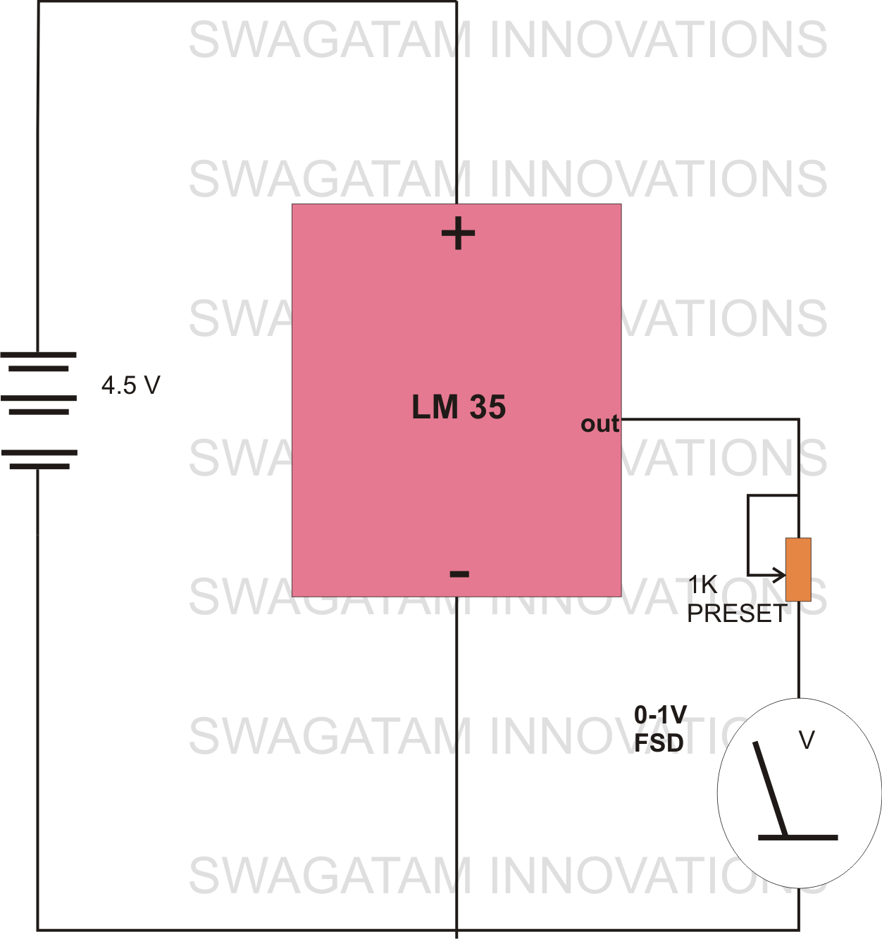
The circuit diagram provided illustrates a straightforward setup. There is no requirement for complex circuitry; simply connect a 0-1 V full-scale deflection (FSD) moving coil meter across the designated pins of the integrated circuit (IC). Adjust the potentiometer as...
A few years ago, a diode-sensor based RF power meter was built using a 68HC11 microprocessor. Prior to that, an analog RF power meter with a thermal power sensor was developed. The datasheets for logarithmic amplifiers, which promised a...
This circuit illustrates the use of the NE5532 integrated circuit in an FM stereo radio decoder circuit diagram. Features include a simple circuit design utilizing the NE5532 IC. Components involved consist of the IC and additional passive elements. The NE5532...
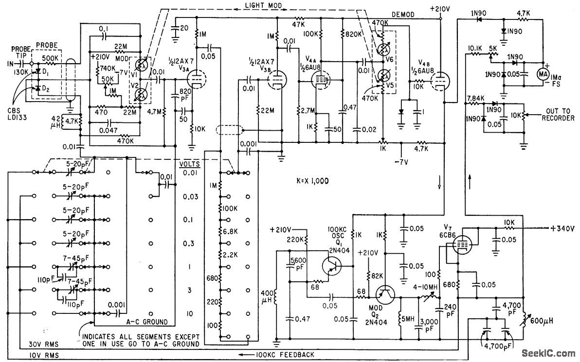
The circuit generates a low-frequency waveform with an amplitude that corresponds to an unknown RF voltage, utilizing a photochopper modulator (VI-V2) as an error detector. This arrangement provides seven voltage ranges from 10 mV RMS to 10 V RMS...