
Single Chip FM Radio Circuit With TDA7000 IC

The Single Chip FM Radio Circuit utilizing the TDA 7000 or TDA 7400 integrated circuits is designed for simplicity and cost-effectiveness, making it an ideal choice for hobbyists and educational projects. The TDA 7000 and TDA 7400 are dedicated FM receiver ICs that incorporate all necessary functions for FM reception, including demodulation and audio output.
The circuit typically consists of a few passive components such as resistors, capacitors, and an antenna. The TDA 7000/7400 IC handles the FM signal processing, allowing for the tuning of FM stations through an external variable capacitor or a potentiometer connected to the tuning input. The audio output is taken from the IC and can be amplified using an additional audio amplifier circuit if higher volume levels are required.
Power supply requirements for the circuit are generally low, with the IC operating typically within a voltage range of 3V to 9V, which makes it suitable for battery-operated devices. The output audio can be connected to a small speaker or headphones, providing a compact and portable FM radio solution.
In summary, the Single Chip FM Radio Circuit based on the TDA 7000 or TDA 7400 is an efficient and economical design for receiving FM radio broadcasts, making it accessible for various applications in consumer electronics.The following circuit shows a Single Chip FM Radio Circuit. This circuit based on the IC TDA 7000 or 7400. Features: low cost FM radio circuit .. 🔗 External reference
Related Circuits
The 22-watt amplifier is straightforward to construct and cost-effective. This circuit can serve as a booster in a car audio system, an amplifier for satellite speakers in a surround sound or home theater setup, or as an amplifier for...
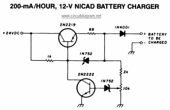
A 12V NiCAD battery charger circuit with a charging rate of 200mA per hour. This circuit initially charges the battery at 75mA until it reaches a full charge, after which the current is reduced to a trickle rate. The...
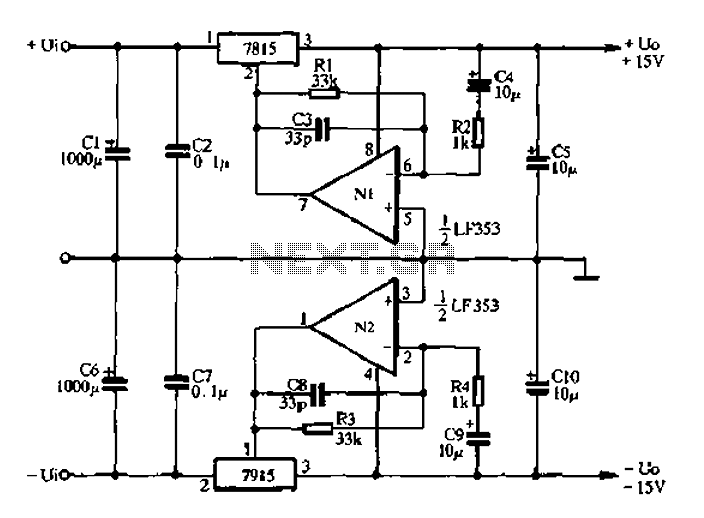
15V active servo power supply circuit The 15V active servo power supply circuit is designed to provide a stable and regulated output voltage of 15 volts, suitable for powering servo motors and other related devices. This circuit typically employs a...
The circuit of the unit is fairly simple, but is a bit irksome to set up. The reason is that obtaining matched FETs is not easy, so I had to make sure that the circuit would work with off-the-shelf...
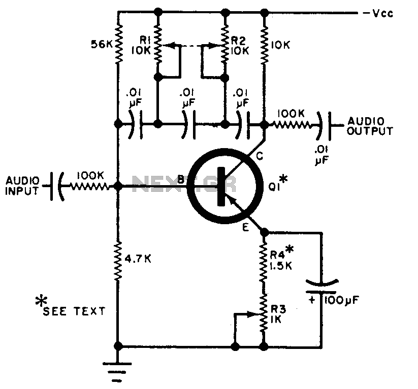
The circuit can be selectively tuned to two closely related tones. The selective frequency is determined by the values of the feedback circuit connected to the collector and base of Q1, which includes capacitors and resistors. When the specified...
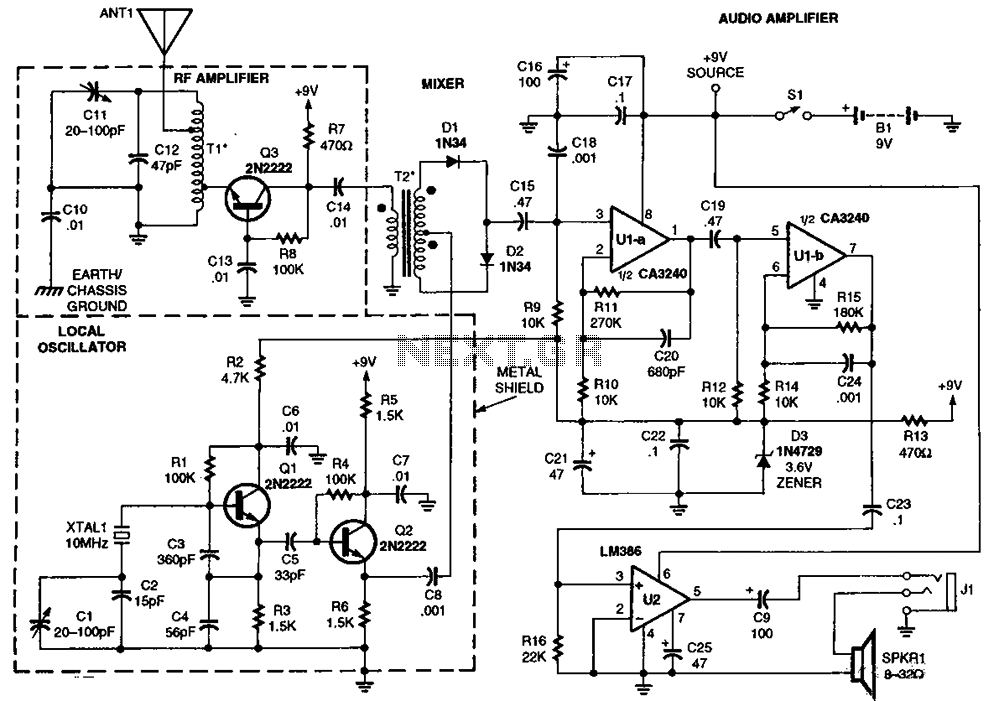
The RF amplifier Q3 connects to diodes D1 to D4 within the mixer. Transistors Q1 and Q2, through transformers T1 and T2, facilitate the injection of liquid oxygen at 10 MHz for diodes D1, operational amplifier U1A, and U1B....