
IC L298 based bidirectional H bridge DC motor control circuit

The bidirectional H-bridge configuration allows for the control of a DC motor's direction and speed by varying the voltage applied to the motor terminals. The L298 IC consists of two H-bridge circuits, enabling control of two motors or a single motor with bidirectional control. The IC operates effectively within a voltage range of 5V to 46V and can output a maximum current of 3A per channel, making it suitable for various applications requiring robust motor control.
The protection diodes (D1 to D4) are critical in safeguarding the circuit against back EMF generated by the motor during operation, especially when the motor is rapidly switched off. These diodes provide a path for the induced current, preventing damage to the L298 IC. Capacitor C2, designated for the logic power supply, ensures stable operation by filtering out noise and voltage fluctuations, while the second capacitor filters the supply voltage, maintaining a consistent power level for the motor operation.
The control logic for the motor is implemented through pins 10, 11, and 12 of the L298. The state of these pins dictates the operational mode of the motor, including forward, reverse, and stop states. A truth table typically accompanies the circuit diagram, detailing the specific pin configurations required to achieve the desired motor action. This setup allows for versatile control in applications ranging from robotics to automation systems, where precise motor function is essential.A bidirectional H bridge DC motor control circuit is shown here. The circuit is based on the IC L298 from ST Microelectronics. L298 is a dual full bridge driver that has a wide operating voltage range and can handle load currents up to 3A. The IC also features low saturation voltage and over temperature protection. In the circuit diode D1 to D4 ar e protection diodes. Capacitor C2 is the logic power supply filter and capacitor C2 is the supply voltage filter. The state of the motor will depend on the logic level of the pins 10, 11, 12 and it is described in the table shown below the circuit diagram. 🔗 External reference
Related Circuits
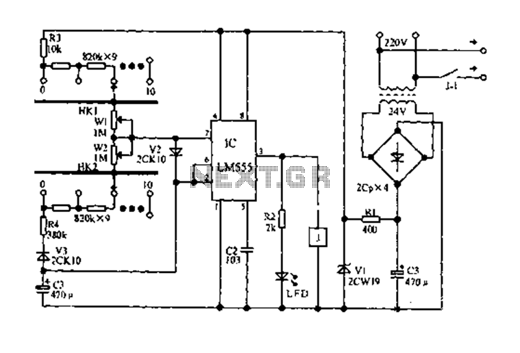
The circuit diagram for an electric start and stop timer is illustrated in the following cycle. It utilizes the LM555 integrated circuit configured as an adjustable duty cycle multivibrator. The circuit includes components C3, KH1, W1, KH2, and W2,...
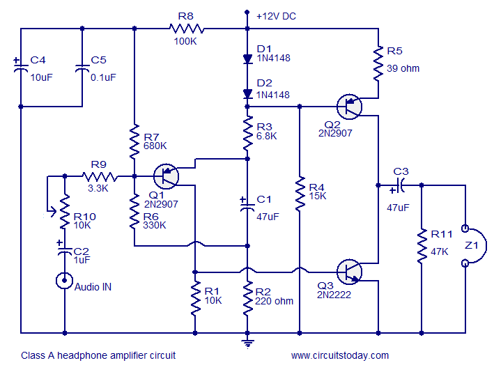
Transistor amplifier circuits that are simple and easy to construct. This includes a headphone amplifier, a four-transistor amplifier, and a low-power amplifier. Transistor amplifier circuits are fundamental components in electronic design, offering various applications ranging from audio amplification to signal...
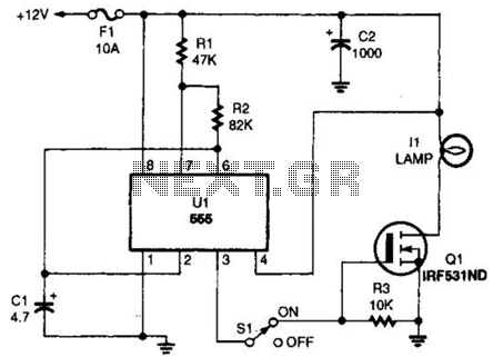
The headlight flasher is a 555 oscillator/timer configured as an astable multivibrator (oscillator). Its input is used to drive the gate of an IRF53IND hexFET, which acts as an on/off switch, turning the lamp on and off at an...
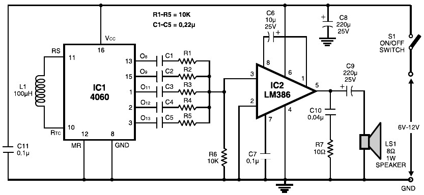
The circuit is built around the popular CMOS oscillator-divider IC 4060 and a small audio amplifier LM386. The IC 4060 functions as a multitone generator. A 100 H inductor is used at the input of the IC 4060, allowing...
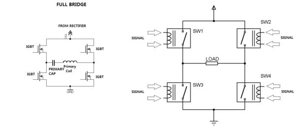
One of the most challenging aspects of constructing a solid-state Tesla coil is the bridge or switching circuit. The bridge switching circuit is the core component of the system. The bridge switching circuit is essential for controlling the power delivery...
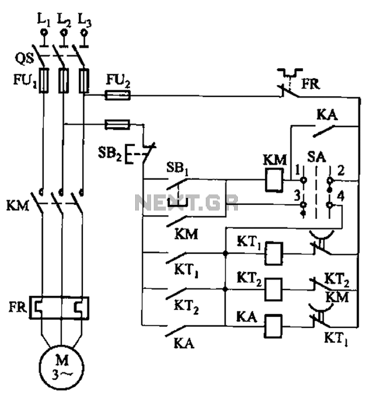
The circuit illustrated in Figure 3-78 utilizes two relays for automatic control, featuring a more complex line structure. This configuration allows for intermittent motor operation. Additionally, it can operate continuously when switch SA is positioned to the right. The circuit...