
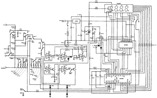
ICL7107 / ICL7106 - Digital Voltmeter

This digital voltmeter is designed for precision measurement of DC voltage, making it a valuable tool in various electronic applications. The core component, the ICL7107, is a versatile analog-to-digital converter (ADC) that allows for accurate voltage readings and is well-suited for low-power applications. The 3.5-digit LED display provides clear visibility of measurements, and the negative voltage indicator enhances usability by allowing the user to identify both positive and negative voltages.
The compact design of the printed circuit board (PCB) facilitates easy integration into existing projects or systems, ensuring that space constraints do not hinder functionality. The requirement for a 5V power supply makes it compatible with a wide range of power sources, further enhancing its versatility.
The ability to adjust the brightness of the LED display is particularly useful in varying lighting conditions, allowing users to optimize visibility according to their environment. The inclusion of 1N4148 diodes for brightness adjustment is a practical feature that can be easily implemented, providing flexibility in display performance.
Moreover, the voltmeter's configuration options for measuring different voltage ranges are crucial for applications requiring specific measurement thresholds. The modification of resistor values to achieve different voltage ranges exemplifies the adaptability of this device. By replacing the 1M resistor with a 100K resistor, users can effectively measure lower voltages with improved accuracy, making the voltmeter suitable for a broader range of applications.
In summary, this digital voltmeter is a compact, efficient, and adaptable tool for measuring DC voltages, offering features that enhance usability and precision in various electronic contexts.This digital voltmeter is ideal to use for measuring the output voltage of your DC power supply. It includes a 3. 5-digit LED display with a negative voltage indicator. It measures DC voltages from 0 to 199. 9V with a resolution of 0. 1V. The voltmeter is based on single ICL7107 chip and may be fitted on a small 3cm x 7cm printed circuit board. The c ircuit should be supplied with a 5V voltage supply and consumes only around 25mA. Brightness of the LED display segments can be varied by adding or removing 1N4148 small signal diodes that are connected in series. Use two 1N4148 diodes for higher LED display brightness. The voltmeter can also be configured to measure different voltage ranges and display higher voltage resolution.
Replacing 1M with 100K resistor will allow to measure 0 - 19. 99V voltages with 0. 01V (10mV) accuracy. 🔗 External reference
Related Circuits
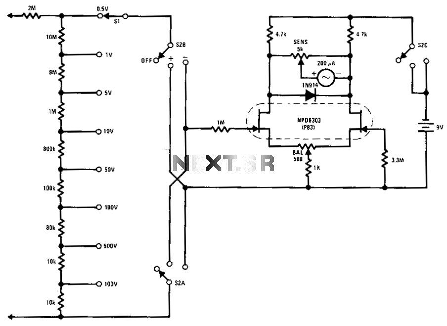
This FETVM replaces the function of the VTVM and eliminates the need for a standard line cord. Additionally, FET drift rates are significantly better than those of vacuum tube circuits, enabling a full-scale range of 0.5 V, which is...
The circuit does not present particular difficulties for somebody that has a small experience. The two circuits are the himself, with a small difference only in their input, when they have they measure voltage or current and in connection...
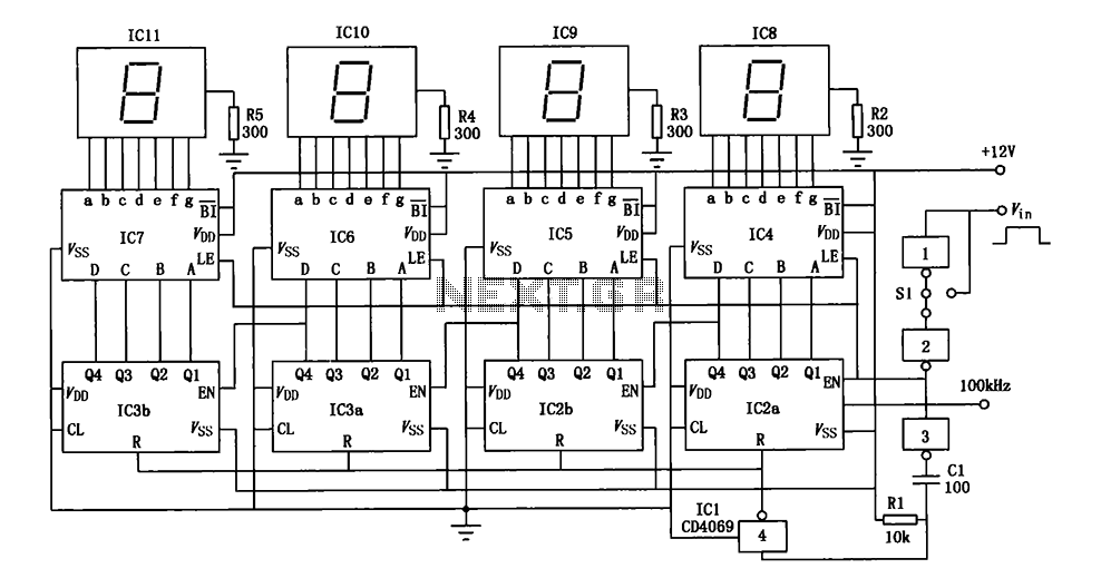
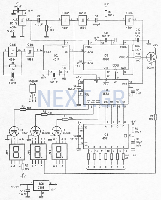
A digital pulse width measurement circuit is presented. It operates with a 100 kHz reference frequency to count the pulse width of the input signal. The count value represents the measured pulse width displayed on four seven-segment LED displays....
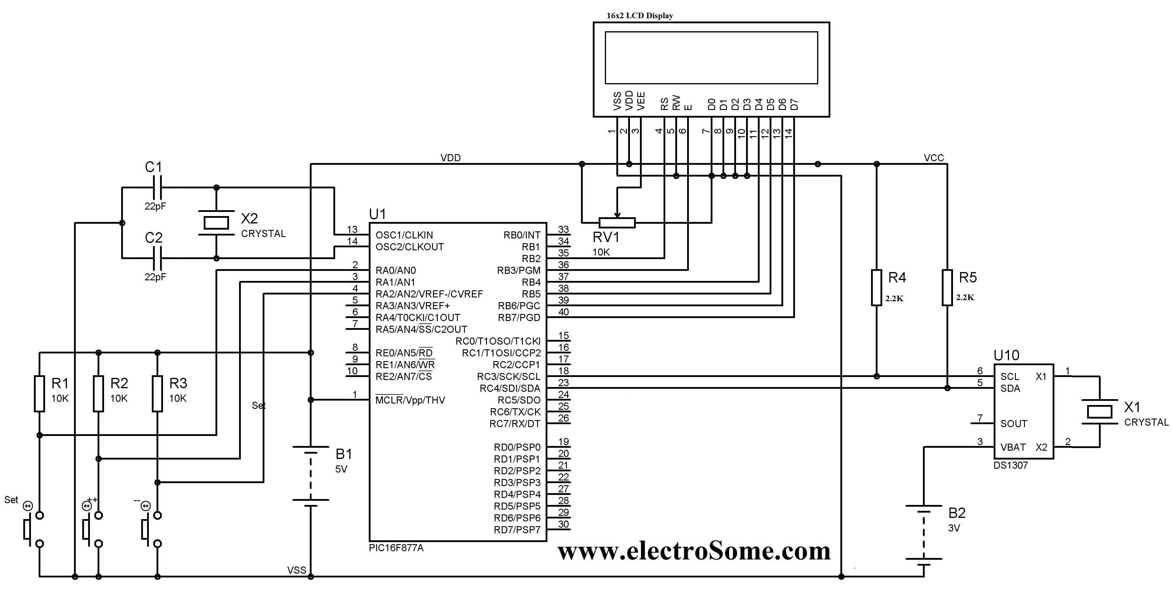
A digital clock can be constructed using a PIC microcontroller, DS1307 real-time clock (RTC), and a 16x2 LCD display. The DS1307 RTC operates in either 24-hour or 12-hour mode with an AM/PM indicator. It adjusts automatically for months with...
The following circuit illustrates the design of a simple digital multimeter circuit diagram. This circuit employs the ADD3501. Features include the combination of voltage measurements, among others. The circuit design for a simple digital multimeter utilizing the ADD3501 integrates several...
This compact device, designed primarily for modelers, provides instantaneous readings of pulse duration in milliseconds (ms). It can measure servomotor positions, typically ranging from 1 ms to 2 ms, and can also perform repetitive or non-pulsed measurements, such as...