
Illumination Intensity Measurement System Diagram

The illumination intensity measurement system is designed to accurately capture and process light intensity levels using a microprocessor-based approach. The system typically consists of several key components, including a light sensor, signal conditioning circuitry, an analog-to-digital converter (ADC), and a microprocessor for data processing and analysis.
The light sensor, which may be a photodiode or a phototransistor, converts the incoming light into an electrical signal. This analog signal is often weak and requires amplification. The signal conditioning circuitry is responsible for filtering and amplifying the signal to ensure it is within the optimal range for the ADC. This stage may include operational amplifiers and passive components to refine the signal quality.
Once the signal is conditioned, it is fed into the ADC, which converts the analog voltage levels into a digital format that can be processed by the microprocessor. The ADC's resolution and sampling rate are critical parameters that determine the accuracy and responsiveness of the illumination intensity measurement.
The microprocessor receives the digital data from the ADC and performs various calculations and analyses. It can display the illumination intensity on an output device, such as an LCD screen, or transmit the data to a computer or other devices for further processing. The microprocessor may also include firmware that allows for calibration, data logging, and communication with other systems.
Overall, the illumination intensity measurement system is an essential tool for applications that require precise light level monitoring, such as in environmental studies, photography, and architectural lighting design. The system's ability to provide real-time digital data enhances its utility in various fields where light intensity plays a crucial role.This is Illumination Intensity Measurement System Diagram. The data in the microprocessor is always in digital form. This is Illumination Intensity Measurement System Diagram - Part 1. The data in the microprocessor is always in digital form.. 🔗 External reference
Related Circuits
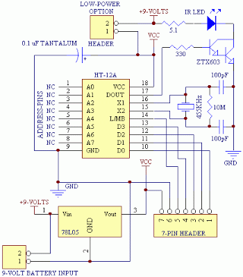
This article demonstrates how to construct a custom version of the Fire-Stick infrared remote control system. The LITEON infrared receiver modules originally integrated into the Fire-Stick have been discontinued, necessitating a redesign of the original circuit boards. The core...
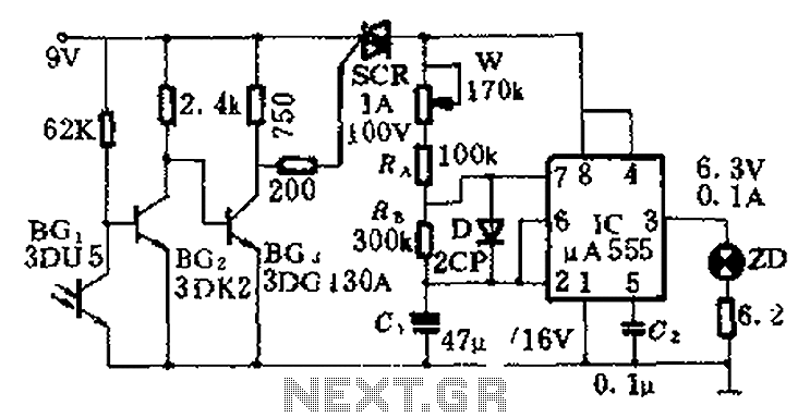
This circuit is designed for nighttime illumination and corridor lighting. During daylight, sufficient light causes BG3 to conduct, preventing the SCR from oscillating. As a result, the circuit remains inactive, and the light does not turn on. At night,...
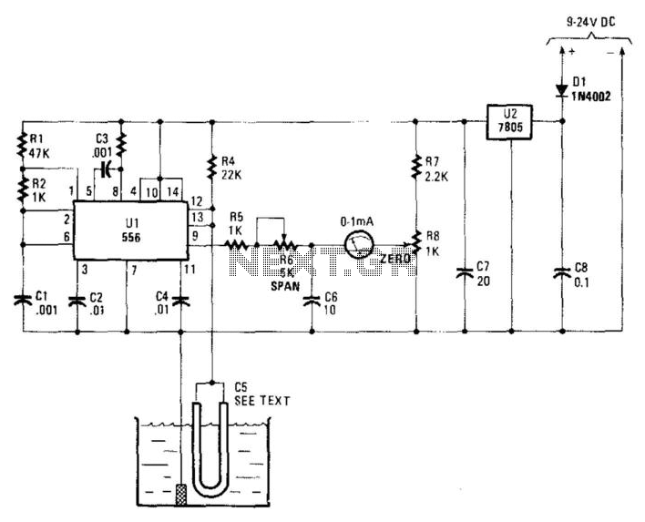
Using a capacitor sensor to detect water levels is a straightforward sensing method. This circuit employs C5, which consists of 10 to 20 inches of #22 enameled wire as one of the electrodes. The oscillator, an NE556 timer, experiences...
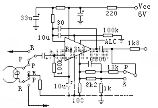
The BA313 is an integrated automatic level control (ALC) circuit designed for use in audio recording preamplifier applications. It is commonly found in cassette tape recorders and comes in a 9-pin dual in-line package (DIP). The circuit features a...
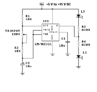
This is a simple LED flasher project that utilizes a common 555 timer integrated circuit (IC) for its operation. It is configured in astable mode, which means its output functions as a square wave oscillator. Two LEDs are connected...
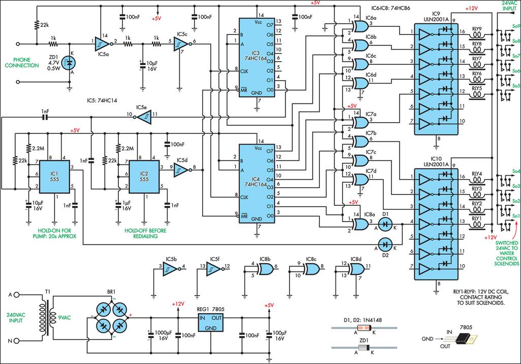
This remotely controlled watering system is cost-effective and easily expandable. It operates in conjunction with a conventional watering timer, enabling remote switching between nine zones. The prototype is designed for use with a bore system, where a deep-well pump...