
Night circuit diagram showing target

This circuit operates based on the principles of light detection and SCR (Silicon Controlled Rectifier) triggering. The BG3 component functions as a light sensor, effectively distinguishing between day and night conditions. During daylight hours, the ambient light level is sufficient to keep the BG3 in a conductive state, which prevents the SCR from entering its conductive phase. This ensures that the connected lighting remains off during the day, conserving energy and preventing unnecessary illumination.
Upon the onset of darkness, the BG3 sensor ceases to conduct, which allows the SCR to be triggered. The SCR is a critical component in this circuit, as it enables the flow of current through the oscillation circuit. The oscillation circuit is primarily driven by an integrated circuit (IC) that generates a square wave output. The frequency of this output is determined by the resistors (Ra, Rb) and the capacitor (C) in the circuit. The relationship between these elements is given by the formula f = 1/T = 1.44/(W + Ra + 2Rb)C, where W represents any additional components that may influence the timing characteristics.
The output of the IC is connected to an LED, which produces a twinkling light effect. This effect is visually appealing and serves to enhance the aesthetic of the corridor or area being illuminated. The flash frequency can be adjusted by varying the values of the resistors and capacitor, allowing for customization based on specific requirements or preferences.
Overall, this circuit effectively combines light sensing, SCR triggering, and oscillation generation to provide an energy-efficient and visually engaging lighting solution for nighttime applications. The use of adjustable components allows for flexibility in design, making it suitable for various environments and user needs. As shown, this circuit is suitable for shooting at night and turned on the lights corridor. During the day due to sufficient light, BG3 conduction, SCR blocking oscillation cir cuit by an IC or the like can not work without voltage, so light is not on. Night, since BG3 off, SCR triggered by conduction, so by the oscillation start oscillation circuit composed of IC, etc., IC 3 ultra-low frequency square wave output continuously, the frequency f 1/T 1.44/(W + Ra + 2Rb ) C, the IC can be seen between 3 and connected to the LED twinkling light, very eye-catching. Ra Rb as C1 adjust the size of flash frequency can be changed.
Related Circuits

To achieve optimal audio reproduction at various listening levels, it is essential to incorporate tone-setting controls that align with the well-documented characteristics of human auditory perception. Specifically, human ear sensitivity exhibits a non-linear response across the audible frequency spectrum,...

This is a very simple FM receiver built using only one transistor. It does not utilize any chips or other active components. The output is connected to earphones; an amplifier circuit is required if the radio is to be...

The circuit diagram is designed for precise control of DC motors. It converts DC voltage into a series of pulses, where the duration of each pulse... The circuit utilizes a pulse-width modulation (PWM) technique to regulate the speed and torque...

The remote control circuit consists of two main components: the transmitter and the receiver. A simple schematic diagram illustrates the remote control setup. The transmitter circuit utilizes a NE555 timer IC to generate a specific frequency. The receiver circuit...

This document outlines the design process of a control circuit for a stepper motor. Given the characteristics of the stepper motor, the control circuit was developed as a state machine that transitions through four output states depending on two...
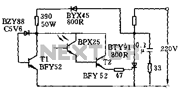
The circuit is designed to activate when the light intensity exceeds 700lx. In this configuration, a phototransistor and the BFY52 transistor are used to trigger the BTY91 thyristor with a current. When light strikes the phototransistor, a positive trigger...