
Car Analog tachometer circuit

R1 = 1 kOhm
R2 = 1 MΩ
R3, R5 = 10 kOhm
R4 = 6.8 kOhm
R6 = see chart
P1 = 5 kOhm
P2 = see chart
C1, C2 = 100 nF
C3 = 220 nF
C4 = 47 µF
D1, D2 = 1N 4001
D3 = 4.7 V zener
IC1 = NE 555
IC2 = CA 3140
M1 = 100 µA meter, or 1 mA
The circuit operates by detecting the ignition pulses generated by the motor's breaker, which produces a rectangular waveform corresponding to the engine's firing frequency. The NE 555 timer (IC1) is configured in monostable mode, allowing it to react to each pulse and generate a corresponding output signal. This output signal is then processed by the CA 3140 operational amplifier (IC2), which converts the pulse frequency into a proportional voltage that drives the analog meter (M1).
The adjustable resistors P1 and P2 allow for calibration of the circuit to ensure accurate readings on the meter. P1 is used to set the characteristics of the output voltage based on the input frequency, while P2 is used to calibrate the meter to read full scale at 10,000 rpm. The use of capacitors (C1, C2, C3, and C4) in the circuit helps stabilize the voltage levels and filter out noise, ensuring a clean signal is delivered to the meter.
The diodes (D1, D2, and D3) serve protection and voltage regulation roles within the circuit. D1 and D2 are standard rectifier diodes that protect the circuit from reverse polarity, while D3, a zener diode, regulates voltage levels to prevent damage to sensitive components.
The circuit's design is suitable for installation in vehicles lacking a built-in tachometer, providing a reliable method to monitor engine speed. Proper installation and calibration are essential for achieving accurate readings, and the circuit can be adjusted to accommodate different engine types and configurations.This is a nice design for people who have no tachometer in the car or on the bike have. The circuit uses two ICs: an NE 555 and a CA 3140. The input of the circuit to the breaker of the motor (on the side that is not connected to ground). Thus, the ignition pulses within the circuit. By the two IC's, this signal then transformed into a speed-dependent voltage which is fed to the meter. The scale of the meter is 0 to 10 000 rpm. The circuit must be adjusted. For this, R6 IC2 temporarily disconnected. On R6 is a voltage of 4 V put. P2 is then adjusted so that the meter full scale deflection. Then again put R6. Then in mass and a voltage is alternating or block whose frequency is known (eg a transformer at 220 V). The speed to which the meter is set to be calculated using the formula: rpm = (30 * f * t) / n. This is the number of revolutions per minute rpm, f is the frequency of the alternating voltage, t is the number of motor cycles (eg 4-stroke) and n the number of cylinders.
This adjustment happens to P1. Remember always that the full scale is 10 000 rpm. R1 = 1 kOhm R2 = 1 M ½ R3, R5 = 10 kOhm R4 = 6.8 kOhm R6 = see chart P1 = 5 kOhm P2 = see chart C1, C2 = 100 nF C3 = 220 nF C4 = 47 uF D1, D2 = 1N 4001 D3 = 4.7 V zener IC1 = NE 555 IC2 = CA 3140 M1 = 100 uA meter, or 1 mA 🔗 External reference
Related Circuits
LCD modules have become a popular means of displaying system messages and status in embedded applications. This application note demonstrates how to interface an SST FlashFlex microcontroller to a typical character LCD module. The SST FlashFlex is an industry-standard,...
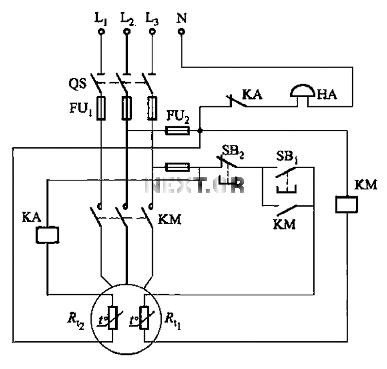
The circuit illustrated in Figure 4-2 employs two thermal resistors. One, designated as Rc, functions as overload protection, while the other, labeled Rt, serves as an alarm. The circuit in question integrates two thermal resistors to monitor temperature changes and...
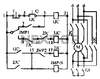
Motor windings are set to connect in a Y configuration while the load is active. The system includes an electric suction mechanism, and the motor is designed to operate under specific conditions. It is rated for 600 revolutions per...

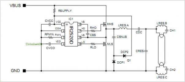
Designing and building a USB sound card has become straightforward with the PCM2702 integrated circuit from Texas Instruments. The PCM2702 is a 16-bit digital-to-analog converter featuring two digital-to-analog output channels. Its integrated interface controller adheres to USB 1.0 standards....
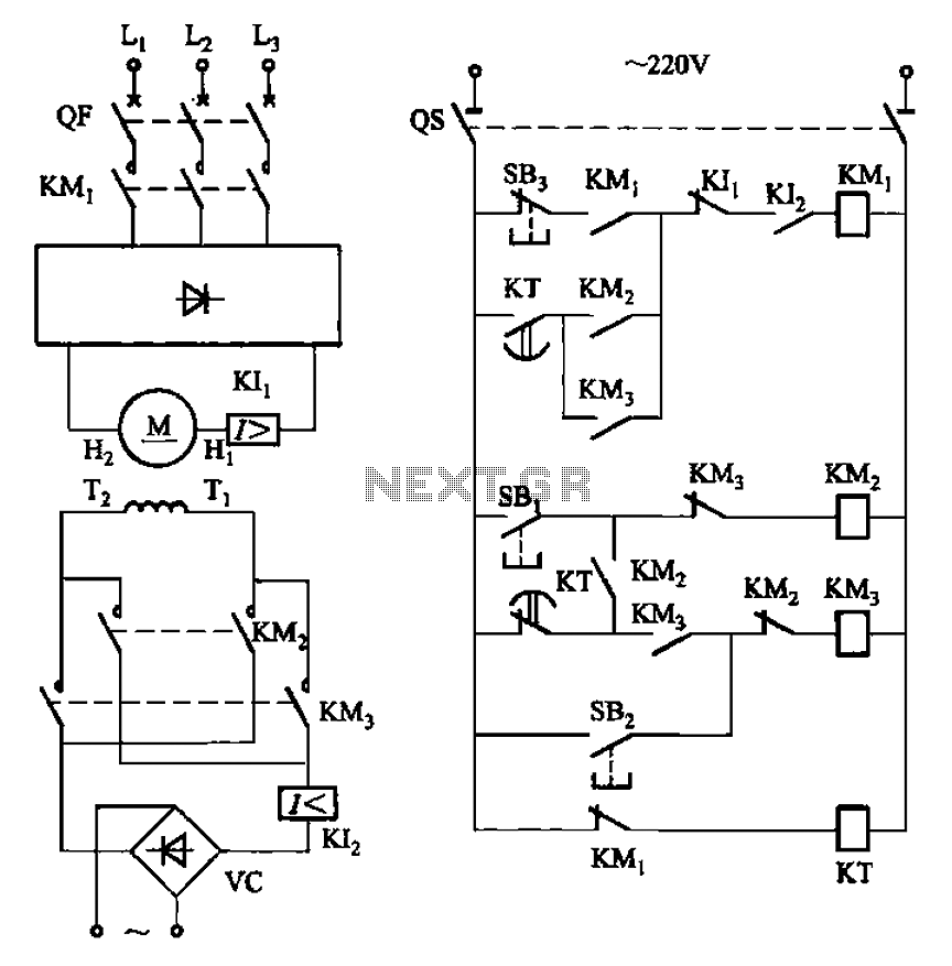
The circuit depicted in Figure 3-193 illustrates a separately excited DC motor. The brake circuit is not activated; therefore, positive reversals occur alternately using a delay action relay, ensuring that the motor reverses direction after coming to a stop. The...
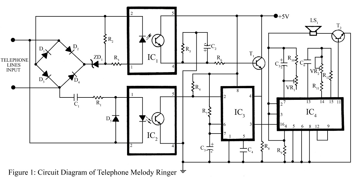
The telephone project described here is a telephone ringer that produces pleasant tunes when a call is received. The tunes generated by this telephone ringer are more melodious and soothing compared to those of traditional telephone instruments and piezo...