
In-Car Charger And Switcher Circuit For SLA Battery

The circuit utilizes an SPDT relay to effectively switch the power from the vehicle's battery to a Peltier cooler, which is a thermoelectric device used for heating and cooling applications. The relay serves as an electronic switch that can control the high current required by the Peltier cooler while being operated by a low control signal.
In this configuration, the relay is connected to the battery's positive terminal and the Peltier cooler. The control signal, which can be derived from a microcontroller or a manual switch, energizes the relay coil, causing the relay to switch its contacts. When the relay is activated, it connects the battery voltage to the Peltier cooler, enabling it to function.
To ensure reliable operation, the circuit may include additional components such as diodes for flyback protection across the relay coil, preventing voltage spikes when the relay is de-energized. A fuse may also be incorporated in series with the power supply line to protect against overcurrent conditions.
The Peltier cooler's performance can be optimized by including a temperature sensor and a control circuit that adjusts the power supplied to the cooler based on the desired temperature settings. This allows for efficient thermal management within the vehicle, enhancing passenger comfort and protecting sensitive electronic components from overheating.
Overall, this circuit design provides a straightforward solution for integrating a Peltier cooler into a vehicle's electrical system, ensuring effective temperature control through reliable power switching.This circuit was devised to switch power to a Peltier cooler in a vehicle. Power to the load from the vehicle s battery is switched by a SPDT relay while.. 🔗 External reference
Related Circuits
The circuit diagram represents a water-activated relay circuit. This circuit employs two transistors configured as a high-gain compound pair. The transistors used are 2N2222A for T1 and T2, which may also be substituted with BC108. The current gain is...

Batteries serve as one of the energy sources available on vessels, utilized during blackouts and emergency situations aboard a ship. These batteries are employed for low-voltage DC systems, such as bridge navigational instruments, and must be kept charged to...
This simple low voltage tester circuit can be used to monitor batteries and other voltage sources for issues, utilizing an LED display and alarm sound. The low voltage tester circuit is designed to provide a reliable method for monitoring the...
LCD modules have become a popular means of displaying system messages and status in embedded applications. This application note demonstrates how to interface an SST FlashFlex microcontroller to a typical character LCD module. The SST FlashFlex is an industry-standard,...
Pressing the pushbutton on the transmitter activates a sound and/or light alert in the receiver. This system operates without wiring or radio frequencies; instead, the transmitted signal is conveyed through the mains supply line. It is suitable for use...
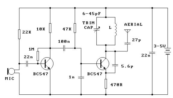
This FM transmitter circuit is very simple and has acceptable transmission. The signal transmitted from this FM transmitter circuit can be received at almost 300 meters in open air. The circuit requires a 3-volt operating voltage and can be...