
Mains Remote-Alert circuit

The described system utilizes a power line communication (PLC) technology, which allows for the transmission of signals over existing electrical wiring. This method eliminates the need for additional wiring or complex installations, making it an efficient solution for alert systems in residential settings.
The transmitter is equipped with a pushbutton switch that, when pressed, generates a signal. This signal is then modulated and superimposed onto the mains voltage, allowing it to travel through the electrical infrastructure of the building. The receiver, connected to the same mains supply, detects this modulated signal and responds by activating an alert mechanism, which can be either an auditory sound or a visual light indicator.
To ensure effective communication between the transmitter and receiver, both devices must be powered from the same electrical circuit. This requirement is crucial, as the signal relies on the integrity of the mains supply line for transmission. The performance of the system is influenced by factors such as the quality of the electrical connections, the presence of interference from other devices, and the overall layout of the electrical wiring within the building.
Installation is straightforward; users simply need to plug the transmitter and receiver into available wall sockets. This plug-and-play feature enhances the system's usability, allowing for quick deployment in various environments. The range of the system can vary based on the electrical setup, but it generally provides reliable operation throughout a typical residential structure.
In summary, this alert system offers a convenient and effective solution for notifying individuals of events or conditions within a home, leveraging existing electrical infrastructure for seamless communication.Pressing the pushbutton of the transmitter, a sound and/or light alert is activated in the receiver. The system uses no wiring or radio frequencies: the transmitted signal is conveyed into the mains supply line. It can be used at home, in any room from attic to cellar, simply plugging transmitter and receiver in the wall mains sockets.
Transmission range can be very good, provided both units are connected to the mains supply within the control of the same light-meter.. 🔗 External reference
Related Circuits
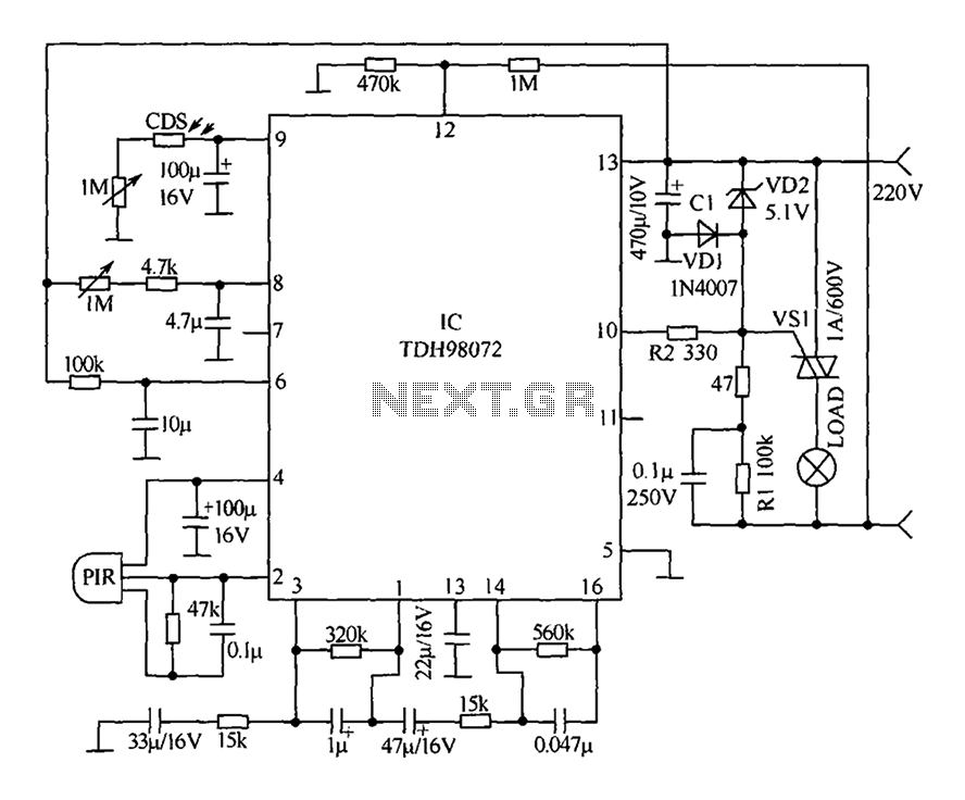
The circuit primarily consists of a new pyroelectric infrared sensor device, TDH98072, which features a special composition. This device is integrated with a control circuit characterized by simplicity, ease of adjustment, and high reliability. Additionally, the device can be...

The circuit is designed for small-signal amplitude modulation (AM). Component C functions as a high-frequency bypass capacitor. Transformers T1 and T2 serve as high-frequency transformers, while the LC resonant circuit operates at the carrier frequency with a passband of...
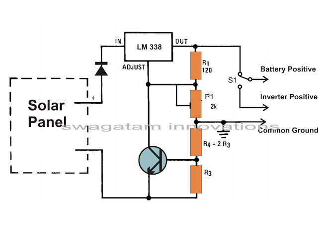
Solar panels are well-known devices that convert solar energy or sunlight into electricity. A solar panel consists of discrete sections of individual photovoltaic cells, each capable of generating a small amount of electrical power, typically between 1.5 to 3...

This circuit resembles an LED clock but utilizes 12 neon indicator lamps in place of LEDs. It operates on two high-capacity nickel-cadmium cells (2.5 volts), providing power for several weeks. A small switching power supply generates the high voltage...
The circuit diagram for a multiple output digital camera power supply using the MAX1802 is illustrated below. The MAX1802 chip features two buck converters and three boost converters. It accepts an input voltage range of 2.5 to 11V and...
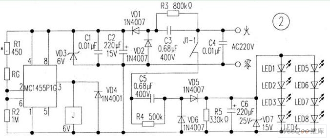
The circuit is depicted in Figure 1, while the electrical schematic diagram is presented in Figure 2. The AC voltage of 220V is reduced by components C3 and R3. The diodes VD1 and VD2 rectify the voltage, and capacitors...