
INA337 high-end configuration of the load current measurement shunt circuit diagram

The INA337 is a precision instrumentation amplifier designed for low voltage applications, particularly in current sensing configurations. The shunt resistor Rs is a key component in this setup, and its value must be carefully chosen to ensure that the voltage drop remains within the specified limits while providing adequate sensitivity to changes in load current. Typically, Rs is selected based on the expected maximum load current and the desired voltage drop, ensuring that the voltage does not exceed the 100 mV threshold, which could lead to saturation of the amplifier and loss of accuracy.
The output filter network, consisting of resistor R0 and capacitor C0, plays a vital role in stabilizing the output signal from the INA337. This filter reduces high-frequency noise that may be present in the measurement due to external electromagnetic interference or inherent circuit noise, thus ensuring a cleaner signal for further processing or display. The design of R0 and C0 should be tailored to the specific application requirements, considering factors such as the desired cutoff frequency and the load characteristics.
In summary, the INA337 circuit configuration is essential for accurate load current measurement, relying on the precise selection of the shunt resistor and effective output filtering to maintain signal integrity. Proper implementation of this circuit allows for reliable monitoring of load conditions in various electronic applications, contributing to improved performance and efficiency. As shown in FIG INA337 constituted by the end of the load current measuring shunt circuit. Will produce a voltage drop when the circuit sampling resistor Rs in series between t he power source and the load, the load current IL flows through Rs, the voltage drop reflects the change in load current. The voltage drop on Rs as an input voltage, after INA337 amplifier output. Select the Rs should pay attention to the voltage drop on Rs formation can not exceed the power supply voltage Rail (Max) 100mV.
R0, C0, is the output filter network, you can filter out the noise output of the circuit.
Related Circuits
This design utilizes four integrated circuits (ICs) and features four input circuits with four independent outputs, along with a single master reset switch. The outputs are configured with light-emitting diodes (LEDs), which can be modified to control lamps or...
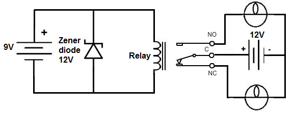
This project involves the construction of a relay driver suitable for both DC and AC relays. Since DC and AC voltages operate differently, the setups for their respective relay drivers require slight variations. A generic relay driver that can...
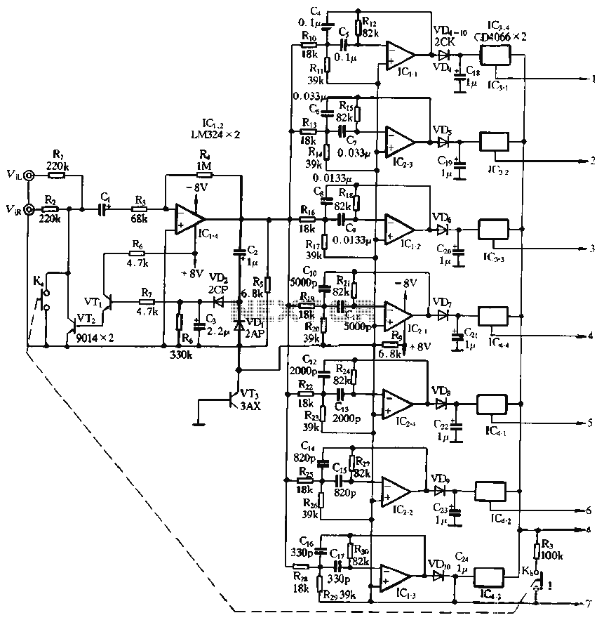
The structure and working principle of this circuit are fundamentally similar to the previous circuit, with some variations in the components used. The circuit is divided into seven bands, with center frequencies selected at 60 Hz, 150 Hz, 400...
The Zener diode may not be providing sufficient current in its breakdown state to activate the transistor. Removing resistor R2 did not resolve the issue. The Zener's voltage selection could be too high, potentially preventing it from regulating the...
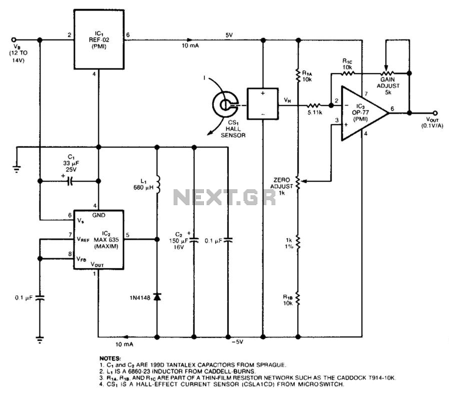
The circuit employs a Hall-effect sensor, which consists of an integrated circuit (IC) situated within a small gap of a flux-collector toroid, to measure direct current (DC) ranging from 1 to 40 A. The current-carrying wire is wrapped through...
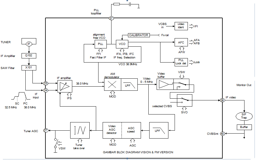
This section is designed to amplify the signal until it reaches the required level. The IF amplifier is equipped with an Automatic Gain Controller (AGC) that regulates the amplification to ensure a constant amplitude output for the video. The...