
Incandescent switching circuit

An incandescent lamp circuit designed for life extension utilizes a two-wire connection, integrating a warm-up mechanism to enhance operational longevity. The circuit operates on a standard 220V AC supply, where the switch closure initiates the flow of current. The negative half-cycle is conducted through diode VD1, energizing the lamp while placing it in a semi-pressure warm-up state.
During the positive half-cycle, the AC current is routed through diode VD2 and resistor R, which serves to charge the capacitor. The capacitor accumulates charge until the voltage across it surpasses the critical threshold of 3V. At this juncture, the voltage regulator tube and thyristor VT reach their breakdown voltage, allowing current to flow through the piezoelectric light bulb, thereby illuminating it.
The warm-up time is a crucial aspect of this circuit, primarily influenced by the values of the voltage regulator and the capacitor. Typically, the warm-up duration is approximately 2 seconds, which is essential for achieving optimal lamp performance. The thyristor VT, which can be triggered with a minimal current, can be substituted with components such as the 2N6565 or other similar micro-way thyristors. The circuit incorporates a 3V, 1/2W Zener diode as the voltage regulator, ensuring stable operation. Additional components do not have specific requirements, allowing for flexibility in the design while maintaining efficient functionality. This schematic design effectively balances performance and efficiency, making it suitable for applications where gradual illumination is preferred.Incandescent is a two-wire connection Life Extension open curse, i A warm-up time than its H K, so scorpionfish life bubble E is quite pregnant. After closing the Ji Guan S, 220V AC only negative 3F week by VD1, S E energizing the lamp made of light, this time for the semi-pressure warm-up state. AC positive half cycle through the VD2 and R. ., R dividing the capacitor (- charging until the voltage across C L rose to more than 3V , it will be behind the breakdown voltage regulator tube vs thyristor VT opened, then only Mou piezoelectric light bulb E electricity. Half way press Warm-up time mainly by the regulator and vs value of the capacitor C determines the capacity of the data when asked preheat icon about 2s .VT can trigger current small micro-way thyristor trigger, such as 2N6565, MC, R100 -type 8 etc.
.vs is 3V, 1 / 2W Zener diode. no special requirements other components.
Related Circuits

The circuit diagram for the receiving portion of a 2.4 GHz wireless keyboard is presented below. The 2.4 GHz wireless keyboard receiving circuit typically consists of several key components that work together to receive and process signals transmitted from the...
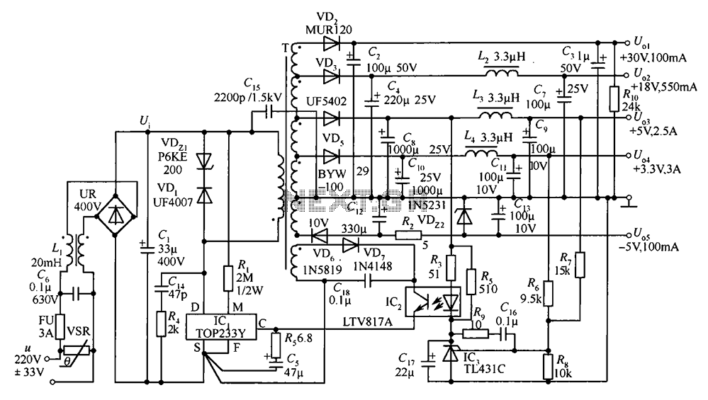
A 35W switching power supply circuit designed for a set-top box output is depicted in Figure 5. It features five distinct voltage outputs: Uo1 (+30V, 100mA), Uo2 (+18V, 550mA), Uo3 (+5V, 2.5A), Uo4 (+3.3V, 3A), and Uo5 (-5V, 100mA)....
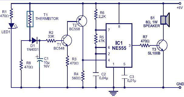
Various fire alarm circuits are discussed, featuring a new design that utilizes a thermistor and a timer. This circuit is straightforward and can be easily implemented. The thermistor exhibits low resistance at high temperatures and high resistance at low...
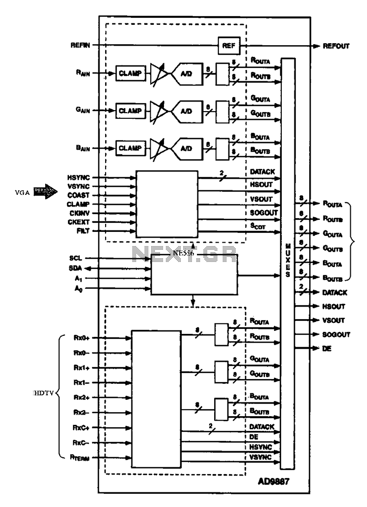
The AD9887, a commonly used video A/D converter for liquid crystal televisions, is capable of converting analog red, green, and blue (R, G, B) signals into digital signal outputs. The AD9887 is a high-performance analog-to-digital converter (ADC) specifically designed for...
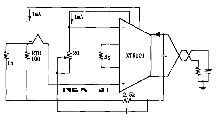
The circuit utilizes a type J RTD (Resistance Temperature Detector), where the resistance value is directly related to the temperature. Calibration of the zero point is facilitated by a 20-ohm adjustment potentiometer as specified by the manufacturer. The schematic features...
The 4017 traffic light circuit connects four legs to the green LED and two legs to the amber LED. This configuration raises the question of whether it could function with only one leg per LED. Each output is activated...