
Incandescent Yeonsu electronic controller 3

The circuit described operates as a soft-start mechanism for a lamp using a combination of diodes, resistors, a capacitor, and an SCR. The switch S, when closed, initiates the charging of capacitor C through diodes VD1 and VD2, with resistor R1 limiting the charging current. The gradual increase in voltage across capacitor C is crucial for controlling the operation of the zener diode VD5, which regulates the voltage and ensures that the SCR VS remains off during the initial charging phase.
During the negative half-cycle of the AC input, the current through resistor R2 and diode VD3 provides the necessary negative trigger current to SCR VS, allowing it to turn on. This initiates the preheating of the lamp H, allowing it to slowly ramp up its brightness. The soft-start feature is essential for preventing inrush current that could damage the lamp or the circuit components.
As the voltage across capacitor C continues to rise and eventually exceeds the zener breakdown voltage of VD5, the zener diode conducts, allowing current to flow to SCR VS, which turns it on fully. This transition marks the end of the soft-start process and allows the lamp H to receive full voltage, resulting in normal operation. The time constant of the soft-start process is determined by the capacitance value of capacitor C and the resistance values in the charging path, which can be adjusted to modify the soft-start duration according to the application requirements.
In summary, this circuit effectively manages the startup of a lamp by controlling the voltage applied to it through a carefully designed sequence of charging, triggering, and regulation, ensuring a smooth transition to full brightness while protecting the components involved. Closing switch S, the power supply positive half cycle, the power by VD1, Rl, VD2 to charge the capacitor C, C at both ends of the electrical pressure gradually increased, but much lower than the threshold voltage of the zener diode of VD5, VD5 in the off state, can silicon vs control because there is no contact Friends of the current in the off state, then no current flows through the bulb H. When the negative half-cycle alternating current, the current through R2 and VD3 to provide SCR vs negative trigger current, vs opened, there was a half-wave alternating lamp H by preheating.
As long as the voltage across capacitor C is less than the regulation value VD5 in an alternating cycle, the current flowing through the lamp H is only half week period, which is the soft-start process of the lamp. Over time, C voltage across the rising, when raised to well over VD5 when regulation value, VD5 conduction, and provide contact pull-up current SCR vs, so in alternating positive half weeks, vs also opened pass, when the soft-start process ends bulb, the bulb H enters full voltage power supply status.
Soft start time mainly by the capacitance C of the decision capacitance.
Related Circuits
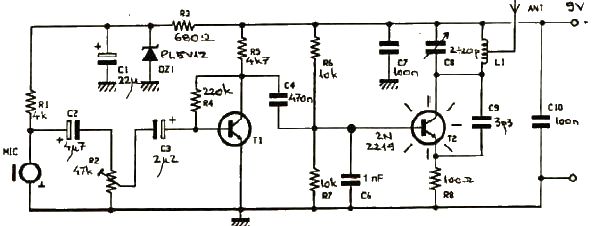
This FM transmitter electronic project operates in the FM band with a transmission power of approximately 250 mW. The circuit is straightforward and utilizes common transistors and electronic components. The T1 transistor, which may be a BC107, BC171, or...
The add-on circuit presented here is useful for stereo systems. This circuit has provision for connecting stereo outputs from four different sources/channels as inputs and only one of them is selected/connected to the output at any one time. When...

The basic die circuit is provided. A 555 timer, IC1, is configured as an astable multivibrator that generates clock pulses. These pulses are sent to a divide-by-six counter, IC2, whose outputs are decoded by gates N1 to N6 to...
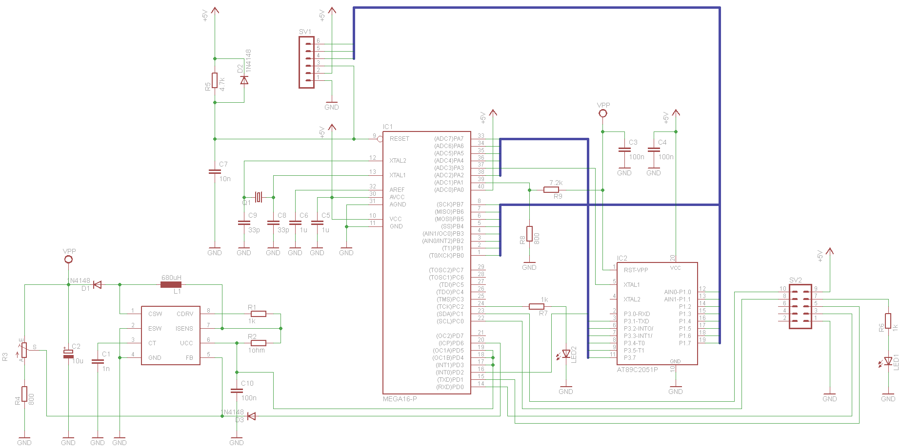
This project has been set aside for several years. It was initially intended for programming old 8051 microcontrollers, which have since become obsolete. The project was recently revisited due to the need for a programmer for the Atmel Xmega...
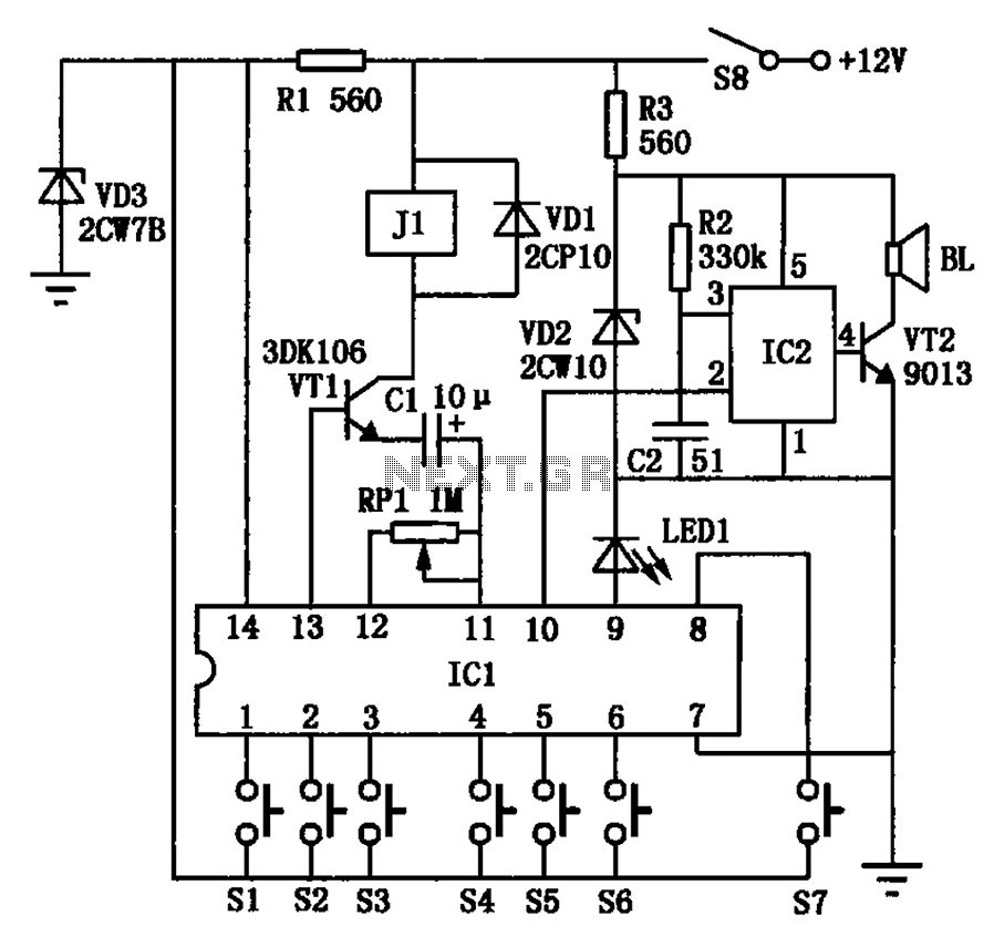
The automotive electronic locks circuit principle is illustrated with the dedicated lock IC 5G058. It features an external key switch connected to the positive power supply. The circuit includes six valid input keys, unlock keys S1 to S6, which...
This circuit utilizes a +5 V reference output and an operational amplifier (op amp) to level shift and amplify the 2.1 mV/°C Tempco output into a voltage signal that varies with ambient temperature. Different scaling options can be achieved...