
Schematic Diagram 250mW FM transmitter electronic circuit

The FM transmitter circuit is designed to provide a compact and efficient solution for low-power audio transmission. The choice of transistors such as BC107 or BC171 ensures that the circuit maintains a reasonable level of performance while being readily available and cost-effective. The audio preamplifier stage, using transistor T1, is critical for capturing sound from the microphone and boosting it to a suitable level for modulation.
The variable resistor R2 plays a significant role in controlling the gain of the audio signal, allowing the user to tailor the audio input to prevent distortion and ensure optimal transmission quality. Care should be taken to avoid overmodulation, which can occur if the audio signal is too strong, leading to interference and loss of clarity in the transmitted audio.
The Hartley oscillator configuration formed by T2 is essential for generating the FM signal. The frequency of the oscillator is determined by the values of C8, C9, and L1. The tuning capability provided by these components allows the user to select a specific frequency within the FM band, accommodating different broadcasting needs. The design of the L1 coil, with its specified number of turns and dimensions, is crucial for achieving the desired inductance and ensuring stable operation of the oscillator.
Overall, this FM transmitter project exemplifies a practical application of basic electronic components to create a functional device for audio transmission. Proper assembly and tuning of the circuit will yield a reliable transmitter suitable for various audio broadcasting applications.This FM transmitter electronic project works in FM band and it has a transmission power around 250mW. This FM transmitter electronic circuit is very simple and is based on some common transistors and electronic parts.
T1 transistor can be a BC107, BC171 or equivalent, and is used as an small audio preamplifier that amplify the audio signal from t he microphone. Adjusting the R2 variable resistor, audio signal level from the input ( microphone ) can be adjusted until will be delivered to the T1 preamplifier (an over amplified signal applied to T1 can produce an overmodulation). From T1, signal is delivered to T2 which form an Hartley oscillator (frequency of this oscillator depends of C8, C9 and L1).
The transmitter frequency oscillator works in FM band 87. 5-108 MHz and can be set, adjusting C8 capacitor and L1 coil. L1 coil must have four turnings on a 0. 8-1 mm cylinder support with a 6 mm diameter (space between each wire must be around 1 mm ). 🔗 External reference
Related Circuits
Currently, a basic MOSFET amplifier or power amplifier is designed to deliver an output power of ±100 Watts RMS with an 8 Ohm load, or ±160 Watts RMS with a 4 Ohm load. The simplicity of this circuit results...
Motor Bike Headlight Controller Circuit. This circuit automatically turns a motorcycle's headlight on and off, independently of both the light and ignition switches, provided the battery is fully charged. The first stage... The motorcycle headlight controller circuit is designed to...

This document outlines a CMOS circuit designed for time adjustment in a spot welder. The circuit allows for the selection of a number of cycles, ranging from 1 to 99, with practical applications typically using around 10 cycles. The...
With this circuit mounted in or near every phone in the house, it will allow users to know if the phone is being used and not to pick up the phone. When a phone is taken off hook, the...

In conventional applications, switching-regulator integrated circuits (ICs) regulate the output voltage (VQVT) by controlling the current through an external inductor. However, the IC in configuration A utilizes a diode-capacitor network in place of the inductor, providing comparable performance for...
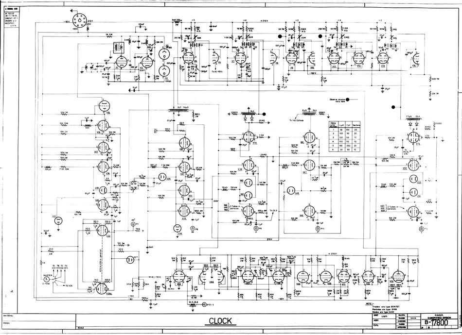
A hard copy schematic diagram related to the computer CSIRAC. The schematic diagram illustrates the detailed connections between all components in the circuit. It is used for building the circuit and later for testing. For CSIRAC, the most common...