
Stereo channel controller

The described circuit functions as an automatic audio source selector for stereo systems, allowing seamless transitions between multiple audio sources. The core of the circuit utilizes two CD4066 integrated circuits, each containing four analog switches, to manage the selection of audio channels. These switches are activated by a CD4017 ring counter, configured to function as a 4-bit counter, ensuring that only one audio source is connected to the output at any given time.
Upon powering the circuit, channel A is selected by default, with the audio output connected to AR and AL for stereo output. The circuit continuously monitors the audio presence in the selected channel. If no audio is detected, the circuit introduces a wait time, adjustable via preset VR1, before automatically switching to the next channel in sequence. This process continues until an audio signal is detected, ensuring that the user always receives audio from an active source.
For manual control, a skip switch (S1) is provided, allowing the user to override the automatic selection and choose a different channel if desired. The status of the selected channel is visually indicated by corresponding LEDs, which illuminate based on the active channel.
The threshold audio levels for the left and right channels can be independently adjusted using presets VR2 and VR3, allowing for tailored sensitivity based on the specific audio sources connected. The KA2281 IC plays a dual role by not only providing audio level indication but also controlling the NE555 timer, which generates the clock signal for the CD4017. The timer operates in astable mode, ensuring a continuous clock pulse as long as the transistor T1 is in a non-conducting state.
In summary, this circuit effectively manages multiple audio sources, providing both automatic and manual selection capabilities, with adjustable parameters to accommodate various audio level conditions, making it a versatile solution for audio system integration. Additionally, the design allows for scalability, enabling the connection of up to ten audio sources with the inclusion of extra CD4066 ICs.The add-on circuit presented here is useful for stereo systems. This circuit has provision for connecting stereo outputs from four different sources/channels as inputs and only one of them is selected/connected to the output at any one time. When power supply is turned on, channel A (AR and AL) is selected. If no audio is present in channel A, the circuit waits for some time and then selects the next channel (channel B).
This search operation continues until it detects audio signal in one of the channels. The inter-channel wait or delay time can be adjusted with the help of preset VR1. If still longer time is needed, one may replace capacitor C1 with a capacitor of higher value. Suppose channel A is connected to a tape recorder and channel B is connected to a radio receiver. If initially channel A is selected, the audio from the tape recorder will be present at the output. After the tape is played completely, or if there is sufficient pause between consecutive recordings, the circuit automatically switches over to the output from the radio receiver. To manually skip over from one (selected) active channel to another (non-selected) active channel, simply push the skip switch (S1) momentarily once or more, until the desired channel input gets selected.
The selected channel (A, B, C, or D) is indicated by the glowing of corresponding LED (LED11, LED12, LED13, or LED14 respectively). IC CD4066 contains four analogue switches. These switches are connected to four separate channels. For stereo operation, two similar CD4066 ICs are used as shown in the circuit. These analogue switches are controlled by IC CD4017 outputs. CD4017 is a 10-bit ring counter IC. Since only one of its outputs is high at any instant, only one switch will be closed at a time. IC CD4017 is configured as a 4-bit ring counter by connecting the fifth output Q4 (pin 10) to the reset pin.
Capacitor C5 in conjunction with resistor R6 forms a power-on-reset circuit for IC2, so that on initial switching on of the power supply, output Q0 (pin 3) is always high. The clock signal to CD4017 is provided by IC1 (NE555) which acts as an astable multivibrator when transistor T1 is in cut- off state.
IC5 (KA2281) is used here for not only indicating the audio levels of the selected stereo channel, but also for forward biasing transistor T1. As soon as a specific threshold audio level is detected in a selected channel, pin 7 and/or pin 10 of IC5 goes low.
This low level is coupled to the base of transistor T1, through diode-resistor combination of D2-R1/D3-R22. As a result, transistor T1 conducts and causes output of IC1 to remain low (disabled) as long as the selected channel output exceeds the preset audio threshold level.
Presets VR2 and VR3 have been included for adjustment of individual audio threshold levels of left and right stereo channels, as desired. Once the multivibrator action of IC1 is disabled, output of IC2 does not change further. Hence, searching through the channels continues until it receives an audio signal exceeding the preset threshold value.
The skip switch S1 is used to skip a channel even if audio is present in the selected channel. The number of channels can be easily extended up to ten, by using additional 4066 ICs. 🔗 External reference
Related Circuits
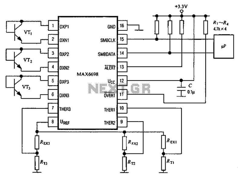
Channel 7 presents a circuit diagram of a smart temperature sensor using the MAX6698. This circuit includes three transistors (VT1, VT2, and VT3) and three thermistors (RT1, RT2, and RT3). An internal reference voltage source is provided via resistors...
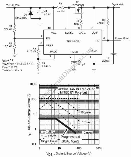
This is a positive high-voltage hot swap controller circuit with a power limiter. This circuit utilizes the TPS2491 or TPS2490, as both of them have specific features. The positive high-voltage hot swap controller circuit is designed to safely connect and...
Integrated AF power amplifiers have experienced significant advancements in recent years, offering enhanced power and ease of use. The TDA1519C from Philips features two power amplifiers that provide 11 W per channel in stereo mode or 22 W in...
The UBA2021 can be utilized as a 600 V lamp controller and half-bridge driver integrated circuit (IC) for high-power applications. It is designed for long-life compact fluorescent lamp (CFL) and tubular fluorescent lamp (TL) applications. The UBA2021 is a versatile...
The power supply section is the important one. It should deliver constant output regulated power supply for successful working of the project. A 0-12V/500 mA transformer is used for this purpose. The primary of this transformer is connected in...
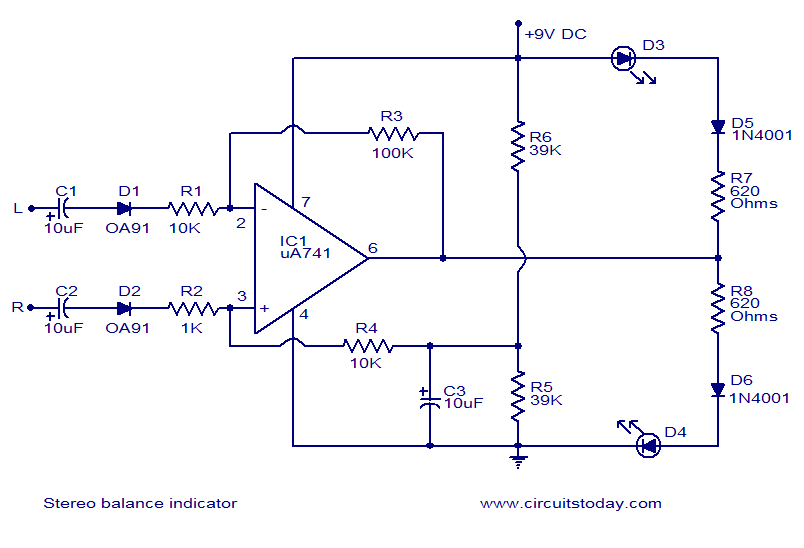
This is one of the simplest stereo balance indicator circuits available. The circuit provides a visual indication using two LEDs, which represent the difference in balance between the left and right channels of a stereo system. It is based...