
Increasing Regulator Current

The circuit utilizes a 78xx series voltage regulator, specifically the 7812, which provides a regulated output of 12V. This regulator is designed to handle a maximum output current of 1A under normal circumstances. However, for applications requiring higher current, a power transistor can be integrated into the circuit to augment the output.
In this configuration, the 7812 regulator maintains the output voltage by regulating the base of the power transistor, typically an NPN type such as the TIP3055 or similar, which is capable of handling higher currents. The base of the transistor is connected to the output of the 7812 through a resistor, which limits the base current. When the load current exceeds 650mA, the voltage drop across the 7812 causes the transistor to turn on, allowing it to supply additional current to the load.
The input voltage to the 7812 should be at least 2-3V higher than the desired output voltage to account for the dropout voltage of the regulator. In this case, with an input voltage of 20V, the regulator can effectively maintain a 12V output. The circuit must be designed with careful consideration of power dissipation; therefore, both the 7812 and the power transistor should be mounted on adequate heat sinks to prevent overheating, especially since the load is expected to draw up to 5A.
The overall circuit design should include bypass capacitors on the input and output of the 7812 to stabilize the voltage and filter out any noise. A common configuration would include a 0.33µF capacitor on the input side and a 0.1µF capacitor on the output side. Additionally, thermal protection measures should be implemented to safeguard against excessive temperatures, which could lead to thermal runaway or damage to the components.
The final assembly should be tested under load conditions to ensure that the voltage remains stable at 12V while the load draws the specified current, confirming the effectiveness of the power transistor in providing the necessary additional current.Although the 78xx series of voltage regulators are available with different current outputs, you can boost the available current output with this circuit. A power transistor is used to supply extra current to the load the regulator, maintaining a constant voltage.
Currents up to 650mA will flow through the regulator, above this value and the power transistor will start to conduct, supplying the extra current to the load. This should be on an adequate heat sink as it is likely to get rather hot. Suppose you use a 12v regulator, 7812. The input voltage should be a few volts higher to allow for voltage drops. Assume 20 volts. Lets also assume that the load will draw 5amps 🔗 External reference
Related Circuits
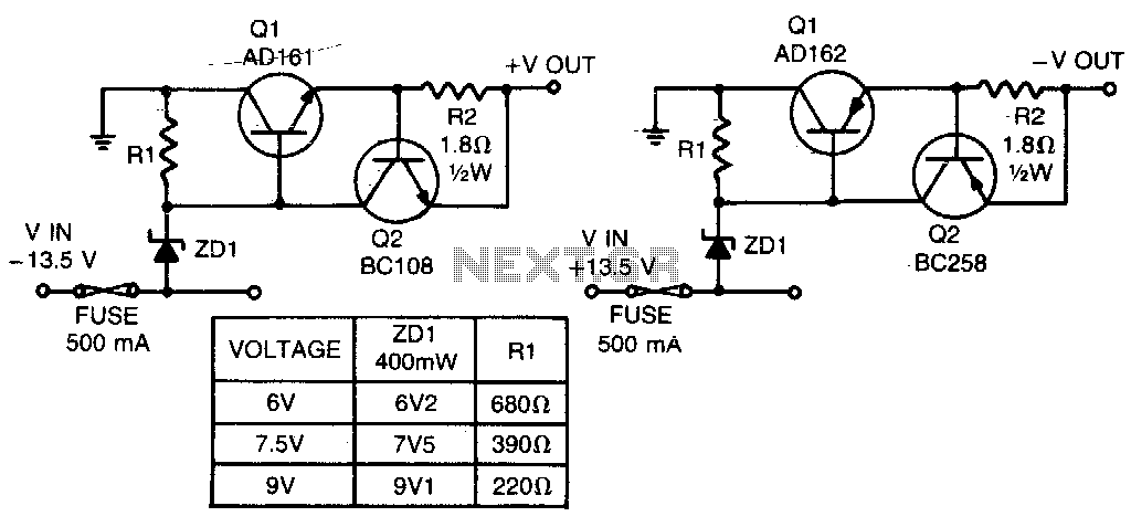
These short-circuit protected regulators provide output voltages of 6, 7, and 9 V from a nominal automobile battery supply of 13 V. They are also compatible with smoothed DC outputs from transformer/rectifier circuits. Two configurations are designed for both...
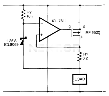
In the circuit presented, a CMOS operational amplifier regulates the current through a p-channel HEXFET power transistor to ensure a constant voltage across the load resistor (RL). The current can be calculated using the formula: I = VREF/RL. The...
This device is designed to serve as a simple and cost-effective comparator, intended for use in a solar cell power supply system where a quick indication of either too low or acceptable voltage is required. The circuit includes one...
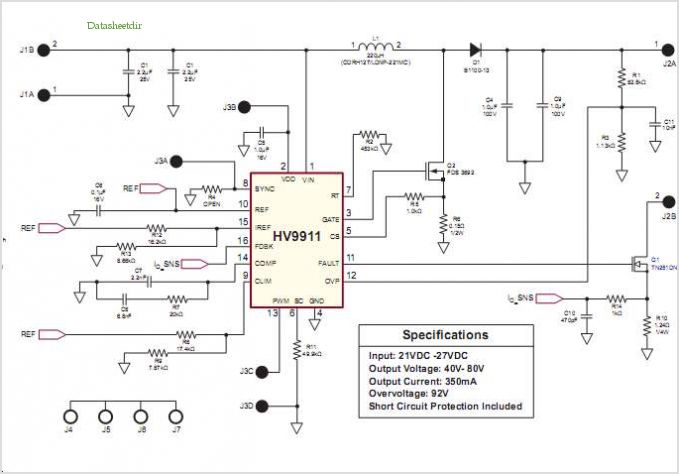
Conventionally, a MOSFET with a voltage rating of 1500V or a Half-Bridge configuration utilizing two MOSFETs rated at 800-900V is employed for Switch Mode Power Supply (SMPS) applications that require input voltages exceeding 380Vac. However, these methods present challenges,...
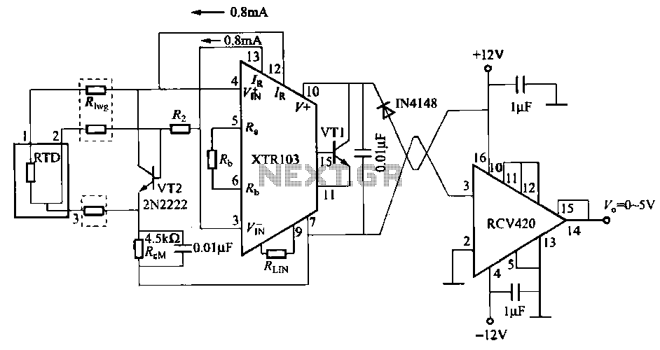
When the RTD temperature sensor is positioned far from the amplifier, the resistance of the sensor leads and their susceptibility to interference and other issues cannot be overlooked. The circuit shown in the figure addresses this problem. It utilizes...
This is a high quality power supply with a continuously variable stabilised output adjustable at any value between 0 and 30VDC. The circuit also incorporates an electronic output current limiter that effectively controls the output current from a few...