
Index 2 - TV Electrical Equipment SeekIC.com

Buffer amplifier IC2-a then provides a low-impedance source to drive IC3, an LM1800 stereo demodulator. When IC3 is locked on a stereo signal, the outputs presented at pins 4 and 5 are discrete left- and right-channel signals, respectively.
In order to provide noise reduction to the L-R signal, you must recombine the discrete outputs into sum and difference signals. Op amp IC4-a is used to regenerate the L-R signal. It is wired as a difference amplifier, wherein the inputs are summed together (+L -, R). Capacitor C18 bridges the left- and right-channel outputs of the demodulator. Although it decreases high-frequency separation slightly, it also reduces high-frequency distortion. The L + R signal is taken from the LM1800 at pin 2, where it appears at the output of an internal buffer amplifier.
The rawL -R signal is applied to IC4-b, a 12-kHz lowpass filter. The L + R signal is also fed through a 12-kHz low pass filter in order to keep the phase shift undergone by both signals equal. Next, the L - R signal is fed to Q2. It allows you to add a level control to the L - R signal path; it provides a low source impedance for driving the following circuits, and it inverts the signal 180 °.
In-version is necessary to compensate for the 180 °inversion in the compander. Next comes the expander stage. At the collector of Q2 is a 75- s de-emphasis network (R27 and C29) that functions just like the network that is associated with Q1. Note that Q2 feeds both Q3 and IC5-a, a -12-dB per octave high-pass filter. The output of that filter drives the rectifier input of IC6, an NE570. The 75-Hz high-pass filter at the rectifier input helps to prevent hum, 60-Hz sych buzz, and other low-frequency noise in the L - R signal from causing pumping or breathing.
The NE570 contains an on-board op amp; its irtverting input is available directly at pin 5 and via a 20-kO series resistor at pin 6. The 18-kQ resistor (R30) combines with the internal resistor and C32 (0. 01 F) to form a first-order filter with a 390- s time constant. Because the internal op amp oper-ates in the inverting mode, the -(L - R) signal is restored to the proper (L - R) form.
The output of the expander drives another 75-Hz high-pass filter, but this one is a third-order type that provides -18 dB per octave rolloff. It is used to keep low-frequency noise from showing up at the output of the decoder. At this point, the (L - R) signal has been restored, more or less, to the condition it was in before it was dBx companded at the transmitter.
(View) This ATV downconverter converts the 420- to 450-MHz ATV band, which is several channels be-tow the lower limit of the UHF band, to channel 3 or 4 for viewing on virtually any TV. The down-converter has a low-noise preamplifier stage and a double-balanced passive mixer for good performance and a wide dynamic range.
That is necessary with today`s crowded UHF bands. The converter draws about 27 milliamperes from a 13. 2-volt dc source, so it can be used 🔗 External reference
Related Circuits
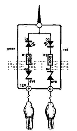
This compact tester is designed for checking vehicle electrical circuits. Two LEDs indicate whether one of the clips is connected to the positive supply line (red) or to ground (green). The unit is powered by the vehicle battery. It...
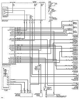
The following circuit illustrates the electrical wiring diagram for the 1997 Chevrolet Malibu. It includes performance circuits for the 2.4L (VIN T) engine and various components. The electrical wiring diagram for the 1997 Chevrolet Malibu is a crucial resource for...
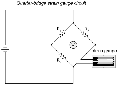
When a strip of conductive metal is stretched, it becomes thinner and longer, resulting in an increase in electrical resistance along its length. Conversely, when the strip is subjected to compressive forces (without buckling), it will widen and shorten....
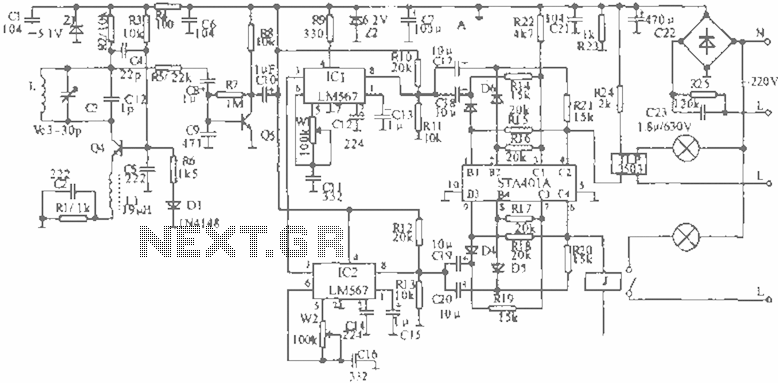
When the infrared receiver tube PH302 receives a signal from the remote control, the CX20106A selected frequency amplifier outputs a low-frequency signal. The low-level signal charges capacitor C through diodes D and R, causing the negative side potential of...
The equation is as follows: If a circuit has a resistance of 25 ohms and a potential of 125 volts, the current drawn in this circuit would be 5 amps. This basic circuit provides a foundational understanding for the...
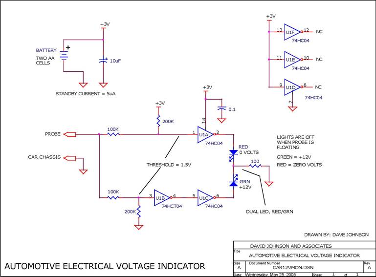
When troubleshooting the 12V electrical system of an automobile, it is beneficial to have a simple voltage indicator tool instead of a voltmeter. This electronic circuit is powered by two AA batteries or two N cells, providing sufficient energy...