
Chevrolet Malibu 1997 Electrical Wiring Diagram

The electrical wiring diagram for the 1997 Chevrolet Malibu is a crucial resource for understanding the vehicle's electrical system. This diagram provides a detailed representation of the wiring layout, illustrating connections between various electrical components and systems within the vehicle.
Key features of the diagram include the performance circuits associated with the 2.4L engine (VIN T), which encompass critical elements such as the ignition system, fuel injection, and various sensors. Each component is represented with clear labels and symbols, allowing for easy identification and troubleshooting.
The wiring diagram typically includes information on wire colors, gauge sizes, and connection points, which are essential for any repair or modification work. It also highlights the relationship between the engine management system and other systems like the battery, alternator, and starter motor, providing insights into how electrical signals are transmitted throughout the vehicle.
In addition to the engine performance circuits, the diagram may cover other essential systems such as lighting, climate control, and audio, ensuring a comprehensive understanding of the vehicle's electrical architecture. This information is invaluable for automotive technicians and DIY enthusiasts alike, facilitating effective diagnostics and repairs.
In summary, the electrical wiring diagram for the 1997 Chevrolet Malibu serves as a vital tool for maintaining and troubleshooting the vehicle's electrical systems, ensuring optimal performance and reliability.The following circuit shows about Chevrolet Malibu 1997 Electrical Wiring Diagram. Features: 2.4L (VIN T) Engine Performance Circuits,. Component: .. 🔗 External reference
Related Circuits
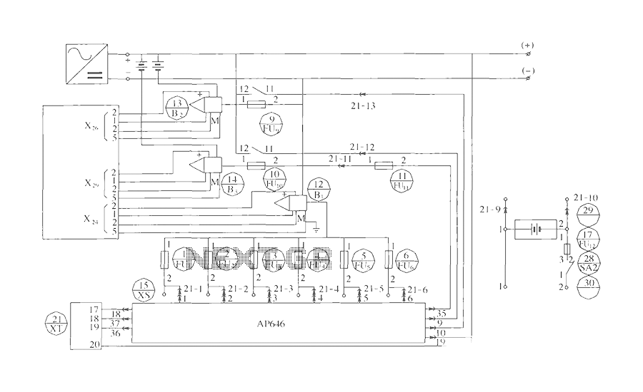
The components include B2 (13) and B3 (14) designated for the Hall current sensor; FU9 (9) and FU10 (10) serve as fuses; an AP646 alarm signal is connected to the fuse board; terminals X24, X26, and X29 function as...
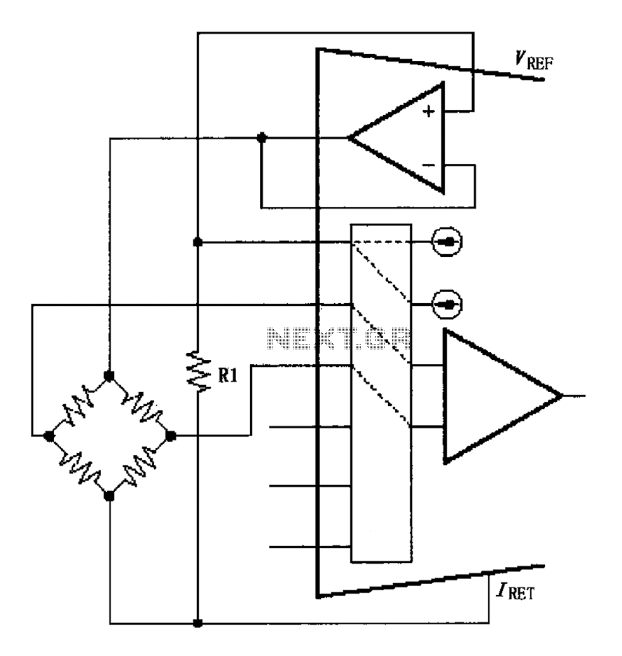
The circuit for the bridge excitation voltage XTR108 is linearized using adjusted algorithms that correspond to the linearization of the RTD response. The excitation voltage VEX is defined as 2IREFR1, where VEX represents the excitation voltage applied at both...
The figure illustrates a digital display pressure measuring circuit diagram. The circuit operates with an additional voltage of approximately 12.8V and draws a current of 30mA. Under maximum gain conditions, the input voltage range is 0.8mV. The zero adjustment...
Many individuals with E46 bi-xenon projectors seek guidance on the proper wiring to prevent solenoid burnout while utilizing only two of the three available wires. Different E46 models feature various wire colors. For instance, one set may have a...
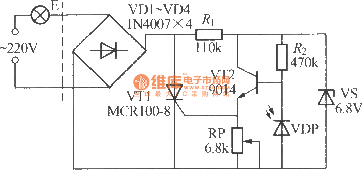
The VDP is a photodiode that exhibits low resistance during the day, approximately 1 kΩ. As a result, transistor VT2 remains off, which keeps thyristor VT1 in the off-state due to the absence of trigger current at the gate,...
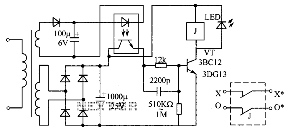
The circuit protection mechanism utilizes optocouplers for on-off control. Under normal voltage conditions, the output from the optocouplers is minimal, and the VT transistor operates in reverse bias. However, if the circuit voltage increases due to reasons such as...