
Inductance Meter Adapter Circuit Turns Your Digital Voltmeter to Inductance Meter

An inductance meter adapter is a vital tool for accurately measuring the inductance of coils and inductors, which is essential for ensuring the desired performance in various electronic applications. This adapter typically interfaces with a digital multimeter or an oscilloscope to provide precise inductance readings.
The design of an inductance meter adapter generally includes a few key components: a microcontroller for processing measurements, a display for visual output, and various resistors and capacitors to create a stable measurement environment. The microcontroller can be programmed to calculate inductance based on the time constant of an RC (resistor-capacitor) circuit when the inductor is connected.
To use the adapter, the inductor is connected to the input terminals. The circuit applies a known voltage across the inductor and measures the resulting current. By analyzing the rise time of the current, the inductance can be calculated using the formula L = V / (di/dt), where L is the inductance, V is the applied voltage, and di/dt is the rate of change of current over time.
Additionally, the adapter may include features such as automatic range selection, calibration options, and the ability to store measurements for later reference. This enhances the usability and effectiveness of the tool for hobbyists and professionals alike, ensuring that inductors are built to specifications and function as intended in circuits.
In summary, an inductance meter adapter is an essential device for anyone involved in DIY electronics, providing the necessary means to accurately measure inductance and improve the quality of hand-made inductors.Measuring inductance is important in making your hand-made inductors, especially when you do-it-yourself (DIY) your coil winding. An inductance meter adapter.. 🔗 External reference
Related Circuits
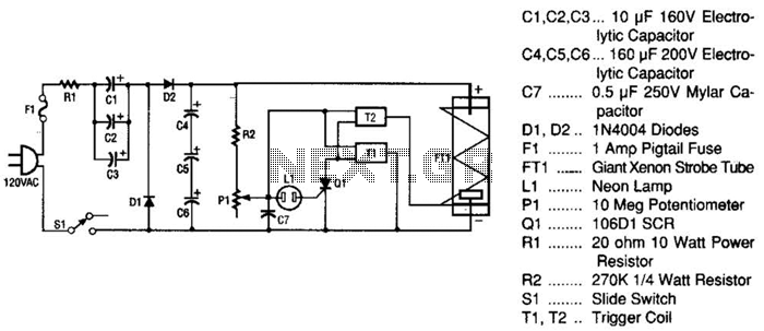
This strobe light operates from standard 120-Vac power. Resistor R1 limits the amount of current applied to the voltage doubler stage, which consists of capacitors C1, C2, C3, and diodes D1, D2, along with capacitors C4, C5, and C6....
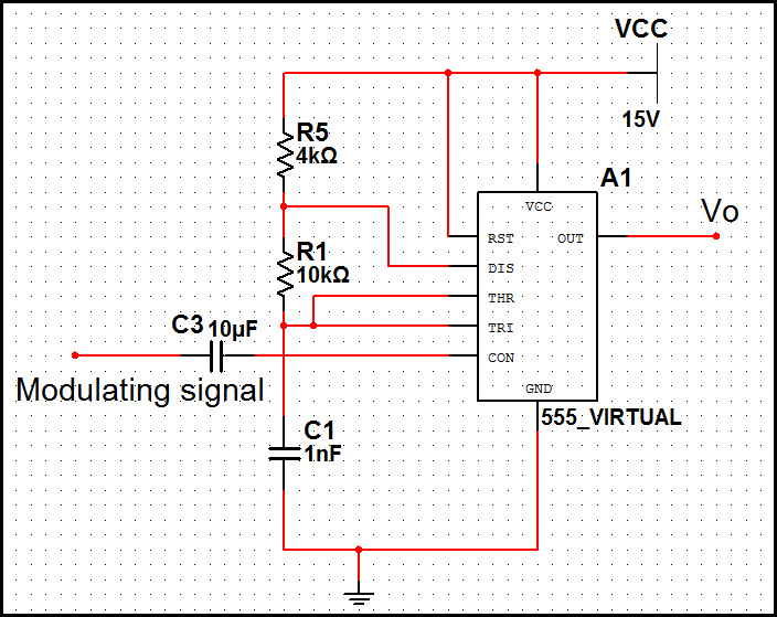
In pulse position modulation, the amplitude and width of the pulses are kept constant, while the position of each pulse with reference to the position of the reference pulse is changed according to the instantaneous sampled value of the...
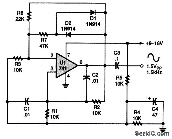
A 741 operational amplifier is configured within a Wien-bridge audio sine-wave oscillator circuit. The components C1, C2, R1, and R2 are responsible for determining the operating frequency of the circuit. By utilizing NPO capacitors and metal-film resistors, the oscillator...
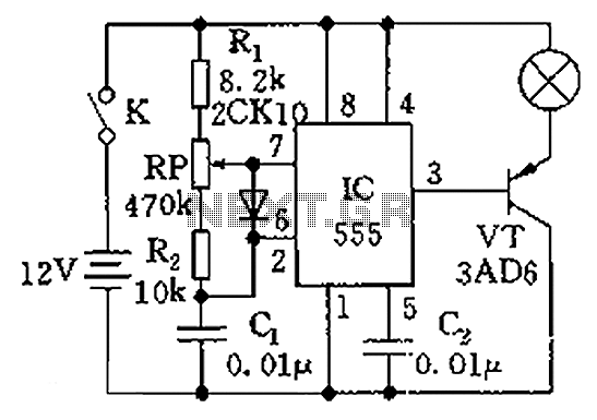
The circuit illustrated in the figure is a dimmer using the 555 timer as the core component. The 555 timer, along with resistors R1, RP, R2, and capacitor C1, forms an astable multivibrator. The oscillation frequency, f, is calculated...
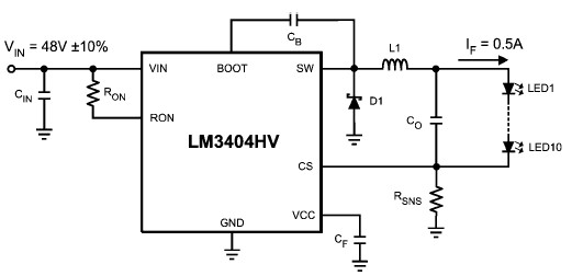
The LM3404 is a monolithic switching regulator that can be utilized to design a simple constant current driver for high-power LEDs. This LED driver project is suitable for automotive, industrial, and general lighting applications. Hysteretic control of the on-time,...

This circuit utilizes a 4049 integrated circuit (IC) to control a 2N2222 switching transistor. The transistor, in turn, drives a piezo transducer known as crystal 1. The circuit design begins with the 4049 IC, which is a hex inverter capable...