
Strobe Light Circuit

The next stage of the circuit is the neon relaxation oscillator and trigger stage, which includes resistor R2, potentiometer P1, capacitor C7, inductor L1, silicon-controlled rectifier (SCR) Q1, and transformers T1 and T2. As the storage capacitor (composed of C4, C5, and C6) reaches full capacity, the voltage divider formed by R2 and P1 applies voltage to capacitor C7. When C7 charges to a threshold voltage level, it triggers SCR Q1. Upon receiving a positive pulse at its gate, Q1 fires, creating a short circuit from anode to cathode. This action discharges most of the energy stored in C7 into the trigger transformers T1 and T2, which have secondary windings connected in series to generate 8 kV. The frequency of the 8-kV pulses is determined by the setting of potentiometer P1 and the value of capacitor C7. Since C7 is a fixed capacitor, only the adjustment of P1 influences the flash rate of the circuit. When an 8-kV pulse is applied from the secondary of T2 (trigger wire) to the trigger lead of the strobe tube, it discharges the storage capacitors C4, C5, and C6, causing the xenon strobe tube to ionize and flash. This cycle continues until power is removed from the circuit board by turning off switch S1 or disconnecting the line cord.
The strobe light circuit is designed to efficiently convert standard AC voltage into a high-voltage pulse suitable for triggering a xenon strobe tube. The voltage doubler stage ensures that sufficient voltage is available for the strobe operation, while the relaxation oscillator provides precise control over the flash rate. The use of diodes for rectification and SCR for triggering enhances the reliability and performance of the circuit. The combination of capacitors in both parallel and series configurations allows for optimized energy storage and discharge, crucial for the rapid operation of the strobe light. The overall design emphasizes simplicity and effectiveness, making it suitable for various lighting applications. This strobe light operates from standard 120-Vac power. Rl limits the amount of current applied to the voltage doubler stage, which is comprised of CI, C2, C3, Dl, D2, C4, C5, and C6. Capacitors CI, C2, and C3 are connected in parallel and form a capacitance of 30 at 160 V. Capacitors C4, C5, and C6 are connected in series and form an equivalent capacitor of about 53 at 480 V.
Diodes Dl and D2 not only rectify the ac voltage, but also complete the voltage doubler stage, which converts the incoming 120 Vac to the appropriately 300 V that are required by the xenon strobe tube. The next stage of the circuit is the neon relaxation oscillator and trigger stage. This stage is made up of R2, PI, C7, LI, Ql, Tl, and T2. As the storage capacitor (made up of C4, C5, and C6) reaches its full-capacity charge, the voltage divider (made up of R2 and PI) applies voltage to capacitor C7. As C7 charges up, it reaches a threshold voltage level, SCR Ql. When Ql has a positive pulse on its gate, it fires (causes a short from anode to cathode). That firing action discharges most of the energy stored in C7 into trigger transformers Tl and T2 (which have secondaries connected in scries to developer 8 kV).
The frequency of the 8-kV pulses is determined by the setting of PI and the value of CT Because C7 is a fixed capacitor, only the setting of PI adjusts the flash rate in this circuit. As soon as an 8-kV pulse is applied from the secondary of T2 (trigger wire) to the trigger lead of FT1, it discharges storage capacitors C4, C5, and C6, which causes it to ionize (flash).
The cycle then repeats itself until the power is removed from the circuit board by turning off SI or removing the line cord.
Related Circuits
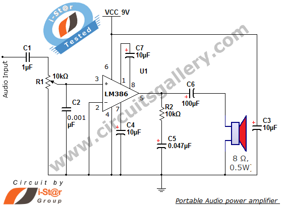
The i-St@r presents a simple mini audio amplifier circuit schematic utilizing the LM386 low voltage audio power amplifier IC. This circuit is designed to power medium-sized speakers from a music player that typically drives only earphones (LM386 headphone). The...

This modem/fax protector can be utilized in telephone-line connections between a PC or a terminal and a remote computer. In this circuit, the surge voltage protectors (SVPs) are rated at 230 V. Additionally, a proper grounding is essential for...
The digital scoreboard circuit is designed to display numerical values ranging from 0 to 9 on a common anode 7-segment display. The circuit employs a 7-segment driver integrated circuit (IC), specifically the 74LS47 or 74LS247. A 555 timer IC...
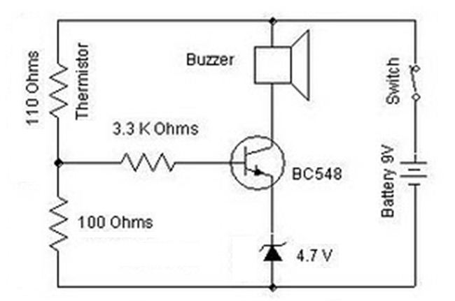
A heat sensor circuit can be utilized to control any device using a heat sensor. In this circuit, a thermistor and a resistor are connected in series, forming a potential divider circuit. The thermistor is of the Negative Temperature...
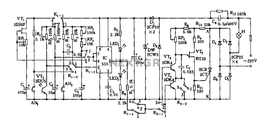
Depending on the external circuit connection, the 555 timer can be configured for various modes such as start delay, trigger delay, multi-harmonic oscillation, and other operational conditions. It functions as a versatile tester with the inclusion of some RC...
The following circuit is an example of how to get power from an RS-232 serial port. It provides regulated +5V power for logic circuits and also unregulated positive and negative power supplies for the RS-232 transmitting circuit. The circuit...