
Temperature Relay Circuit

The temperature relay circuit typically consists of a temperature sensor, a transistor, and a relay. The temperature sensor can be a thermistor or an integrated circuit temperature sensor, which provides an output voltage that varies with temperature. This output is fed into the base of the transistor (T1), which acts as a switch to control the relay.
In this design, the potentiometer (P1) is used to fine-tune the base voltage of the transistor. By adjusting P1, the voltage at the base of T1 can be set to be 0.5V less than the emitter voltage, ensuring that the transistor operates correctly within its active region. This precise adjustment is crucial for accurate temperature detection and relay operation.
When the temperature exceeds the predetermined threshold, the voltage from the temperature sensor will rise, causing the base-emitter junction of T1 to become forward-biased. This will allow current to flow through the collector-emitter path of the transistor, energizing the relay coil. The relay can then activate an alarm system or a fire suppression mechanism.
The circuit may also include additional components such as resistors to limit current, capacitors for stability, and diodes for flyback protection across the relay coil to prevent voltage spikes when the relay is de-energized. Proper layout and component selection are essential to ensure reliable operation and to minimize false triggering due to noise or transient signals.This is a design circuit for temperature relay that can be used to signal a fire or set point for temperature monitoring function. You need to adjust P1 so that T1?s base voltage is 0.5V smaller than the emitter voltage at a temperature a little bit..
🔗 External reference
Related Circuits
The circuits on this page are for motor controls using Push buttons and would typically be found in commercial and industrial installations. The circuits do not show the wiring of the motors themselves as this depends on the particular...
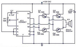
The circuit operates on the principle that insects, such as mosquitoes, can be repelled using sound frequencies in the ultrasonic range (above 20 kHz). It utilizes a Phase-Locked Loop (PLL) integrated circuit, specifically the CMOS 4047, configured as an...

This circuit features open and closed loop contacts (switches 1, 2, 3) that activate the alarm, which remains on for a duration of 5 to 10 minutes. The triggering delay for entrance and exit is set to 27 seconds....
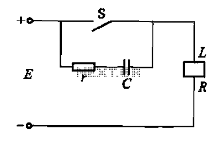
A resistor-capacitor circuit designed to prevent spark blowout. The coil's magnetic energy is converted into electrical energy stored in the capacitance C, effectively suppressing sparks and enhancing safety. The circuit is capable of functioning normally even with reverse polarity....
The completed Solar CD Two LED circuit is presented with components labeled to correspond with the schematic. Although the soldered circuit may appear different from the schematic, the connections remain consistent, which is crucial. To transition from the schematic...

The baby-alert receiver consists of three transistors: Q2, configured as a high-gain linear amplifier; Q3, functioning as both an amplifier and detector; and Q4, which operates primarily as a switch. Additionally, there are several other components involved. The system...