
Mini DDS circuit

The function generator circuit is designed to provide a versatile and efficient means of generating various waveforms for testing and experimentation. The AT2313 microcontroller plays a crucial role in the functionality of the device, executing the programmed logic to control the output waveform characteristics. The R2R resistor network, which acts as the DAC, converts the digital output from the microcontroller into an analog voltage. The network’s design allows for a straightforward implementation while achieving adequate performance for most applications.
The voltage regulator, specifically the MAX603, is essential for maintaining a stable operating voltage for the entire circuit, ensuring reliable performance across varying conditions. The RS232 interface allows for easy communication between the PC and the function generator, enabling users to set parameters such as frequency and waveform type through the Windows application. The choice of using RS232 facilitates compatibility with a wide range of devices, making the function generator accessible for various applications.
The output stage of the function generator may require additional buffering to mitigate the effects of high output impedance, which can lead to signal distortion or loading issues when connected to other circuits. This can be achieved by incorporating an operational amplifier configured as a voltage follower, which would provide a low output impedance while preserving the signal integrity.
Overall, this simple function generator exemplifies an efficient design that leverages readily available components, providing a practical solution for generating a variety of waveforms in a compact and cost-effective package. The system's modular design allows for potential upgrades and modifications, such as the integration of the AD9832 chip in the future, which could enhance the functionality and performance of the generator.A simple function generator. Just to generate a certain frequency. While waiting for the AD9832 chip to arrive, I came up with a very simple version of the DDS synth, using just the 2313 and a resistor network. It`s controlled over RS232 from a small Windows program, and can generate Sine-, Sawtooth-, Trangle- and Sqare-waves ranging from 0.
07 Hz to about 200-300 kHz in 0. 07 Hz steps (depending on your crystal). I wont go into details about how a DDS synth works. Maybe later. The code is pretty simple so you should be able to understand how it works by just reading through it. There`s not much to say about the schematic. It`s as simple as can be. Just 4 major parts. A voltage regulator/switch, a RS232 interface chip, the 2313 and the R2R resistor network. The R2R network is connected to PORTB on the 2313, making it a simple D/A converter and makes it possible to output 256 voltage levels.
Neither the resistor network or port drivers of the 2313 is of perfect linearity, but it works pretty well anyway. But you`ll probably need a buffer stage as the output impedance is rather high (tens of kOhms in my case).
The MAX603 handles the voltage regulation as well as the powerup/shutdown function, and is controlled by the DTR signal on the serial interface. So when you shut down the control program on the PC, the miniDDS will be shutdown, saving battery. The phase accumulator uses 24 bits, which determines the resolution of the output frequency. Maximum available frequency and resolution is also dependent on your crystal frequency : 🔗 External reference
Related Circuits
This circuit generates audio musical notes that can be heard from a distance of up to 10 meters. It consists of two main components: an infrared (IR) music transmitter and an IR music receiver. The IR music transmitter operates...
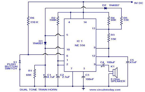
A dual-tone model train horn/sound generator/simulator circuit can be created using two NE 555 timers connected in cascade. However, the circuit diagram presented is designed with the NE 556 integrated circuit, which essentially comprises two 555 timers in a...
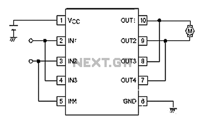
A simple motor control project for forward and backward drive can be implemented using the LB1948M motor driver IC, which features two channels for motor control. The LB1948M is an ideal choice for 12V motor drive systems and can...
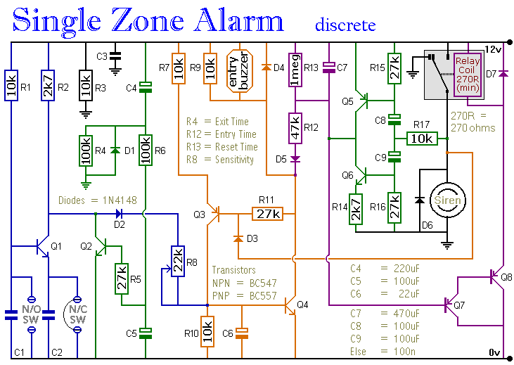
The circuit includes automatic exit and entry delays, a timed bell cut-off, and a system reset feature. It accommodates both normally-open and normally-closed switches, making it compatible with standard input devices such as pressure mats, magnetic reed contacts, foil...
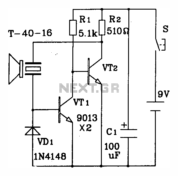
The discrete components ultrasonic transmitting circuit T/R-40-16 is capable of emitting a series of ultrasonic signals at a frequency of 40 kHz. This circuit operates at a voltage of 9V, with an operating current of 25 mA, and can...

The hobby circuit described utilizes a unique approach to generate approximately 12,000 volts with a current of about 5 µA. It employs two silicon-controlled rectifiers (SCRs) that form dual pulse generator circuits. These SCRs discharge a 0.047 µF capacitor...