
Inductive electronic doorbell 1

The inductive electronic doorbell circuit operates by utilizing an inductive switch that detects the presence of a magnetic field, which activates the music generator upon detection. The inductive electrode A serves as the sensing element that responds to the magnetic field generated by a nearby object, such as a person approaching the door. When the magnetic field is detected, it triggers the transistors V1-V4, which act as switches to control the flow of current through the circuit.
The resistor R1 is critical in limiting the current to the transistors, ensuring they operate within safe parameters. The potentiometer RP allows for adjustment of the sensitivity of the inductive switch, enabling customization based on environmental conditions or user preferences.
The music generator circuit, which is driven by the music integrated circuit, produces a melody or sound when the inductive switch is activated. This circuit typically includes additional components such as capacitors and resistors to shape the audio output and ensure proper functioning of the IC. The combination of these elements creates an effective and reliable doorbell system that enhances user experience with its audible alert feature.
Overall, the inductive electronic doorbell circuit exemplifies a practical application of inductive sensing technology and audio output integration, making it a useful addition to modern home automation systems.The inductive electronic doorbell circuit is composed of the inductive electronic switch and music generator circuit, and it is shown in Figure 3-115. Inductive electronic switch circuit is composed of the inductive electrode A, transistor Vl-V4 and the resistor R1, potentiometer RP components.
Music generator circuit by the music integrated circuit IC, resi.. 🔗 External reference
Related Circuits
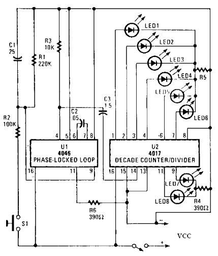
An electronic circuit for a roulette wheel can be constructed using a 4046 Phase-Locked Loop (PLL) that includes a Voltage Controlled Oscillator (VCO), two phase comparators, a source follower, and a Zener diode to generate a low-frequency pulsed output...
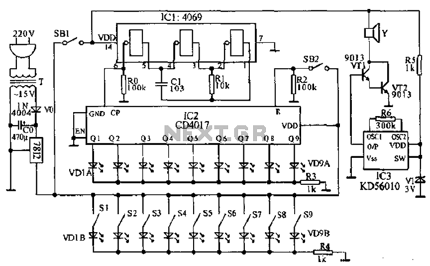
This document presents a principle circuit for electronic games. The main circuit operates in conjunction with the host through the reset button SB2, while the indicators VD1A-VD9A remain off. Prizes, for example, five, are determined by the number of...
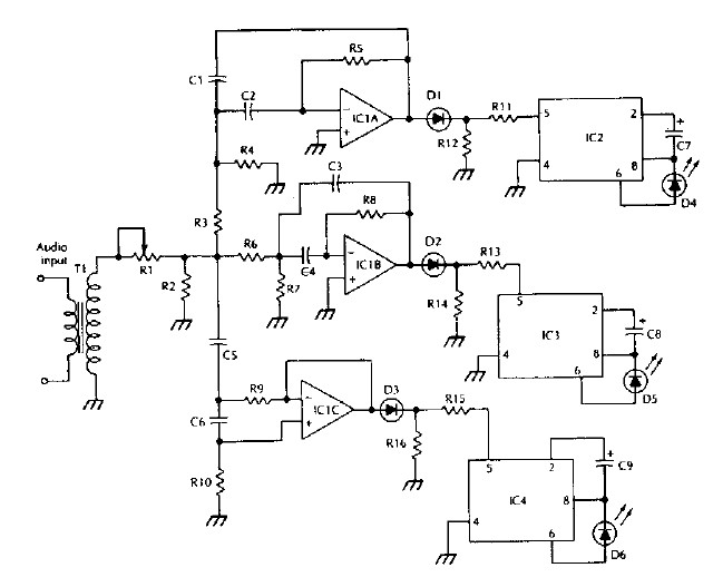
The LM 3909 LED flasher integrated circuit (IC) can be utilized to design various electronic projects. A circuit diagram illustrates the creation of a simple color organ using the LM3909 LED flasher IC. Three active filters process the audio...

This stereo balance indicator circuit diagram is designed using a few common external components. The schematic circuit is simple to build and provides a visual indication with LEDs for left, right, and center balance. Outputs from each channel are...
This circuit is a modified Hartley oscillator that incorporates additional components. The transformer used is a small audio transformer, specifically type LT700. The primary winding is center-tapped with an impedance of 1 kΩ at 1 kHz, while the secondary...

This circuit illustrates the use of the 4011 integrated circuit (IC) for a surge protection electronic circuit diagram. Features include the ability to delay the activation of other appliances connected to the output. The 4011 IC is a quad 2-input...