
4011 IC For Protection Surge Electronic CIrcuit Diagram

The 4011 IC is a quad 2-input NAND gate, which can be employed in various electronic applications, including surge protection circuits. In this specific application, the circuit utilizes the NAND gates to create a delay mechanism that protects connected appliances from voltage spikes or surges.
The basic operation of the circuit involves the use of the 4011 IC to monitor the input voltage levels. When a surge is detected, the circuit will momentarily disconnect the output to prevent damage to the appliances. The delay feature is crucial, as it allows for transient surges to dissipate before re-engaging the output.
The schematic typically includes the 4011 IC connected to a power supply, input surge detection components (such as diodes or varistors), and output control elements (like relays or transistors) to manage the power to the connected appliances. Resistors and capacitors are also included to set the timing for the delay and filter out noise.
This circuit is particularly beneficial in environments where electrical surges are common, providing an essential layer of protection for sensitive electronic devices. The design should ensure that all components are rated appropriately for the expected voltage and current levels to maintain reliability and safety.This circuit shows about 4011 IC For Protection Surge Electronic CIrcuit Diagram. Features: used to delay other appliances connected to the output .. 🔗 External reference
Related Circuits

Using a Motorola MC34118 speakerphone IC, this adapter can be utilized with a standard telephone to enable speaker functionality. The device is powered from the phone line; however, it can also be powered through an external power supply if...

A display tube utilizing a constant current circuit to ensure a steady flow through the tube. The display tube operates on the principle of maintaining a constant current to achieve consistent brightness and performance. The circuit typically comprises a current...
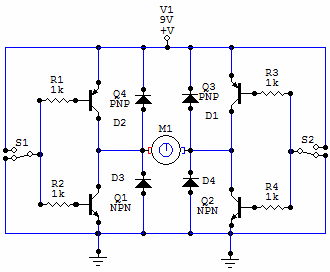
You have 4 transistors, wired as ON OFF switches. Two signal lines allow you to run the motor in one direction, when reversed, the motor runs in the other direction. It's very straightforward to use and build, but be...
This project flashes eight LEDs in an apparently random manner. It uses a 4060 combined counter and display driver IC which is designed for driving 7-segment LED displays. The sequence is not really random because seven of the LEDs...

The circuit is composed of a W7805 positive current source application integration circuit that includes a voltage regulator. The W7805 regulator operates in suspension. A resistor is placed between its output terminal and the common terminal, forming a constant...
The following circuit illustrates a timer circuit with independent mark and space periods. It is based on the 7555 integrated circuit (IC). The high output duration is calculated by T(on) = 0.7 Ra Ct, while the low output duration...