
Industrial & Domestic Electronic Kits
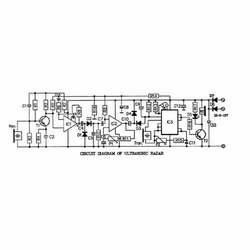
The major advantage is that this circuit is absolutely free from ambient light interference and provides controlled range of about 10 mt without the use of any focusing lens. Transmitter and receiver circuits are described below: Transmitter section consists of a power supply, an oscillator and an output stage.
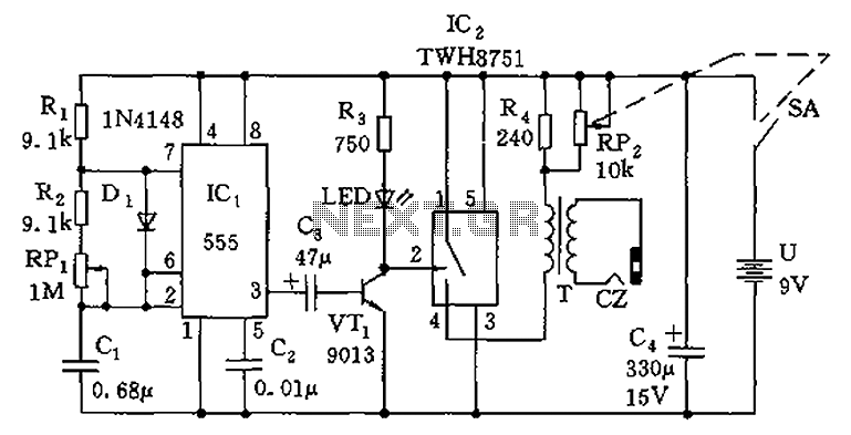
The circuit diagram for transmitter is shown in fig. IC1 is wired as an astable multivibrator with a center frequency of about 26KHz. When switch S1 is pressed, the circuit gets energized, output of IC1 is a square wave. The infrared LED connected at it`s output transmit IR beams modulated at the same frequency. The oscillator frequency can be shifted slightly by adjusting preset VR1. The circuit of temperature switch described here, autometically switches on a device when the temperature rises to about 60 °C. It is a very simple circuit build around IC1, which is operated in monostable mode and temperature sensor diode D1.
At temperature about 60 °C, the sensor triggers IC1, which makes output of IC1 at high level and energises the relay. Also it becomes off as temperature goes below 60 °C. The circuit of Temperature Switch is shown in figure. Sensor Diode D1 in reverse bias is connected to trigger pin2 of IC1. At temperature below 60 °C, the reverse resistance of D1 is very high, which keeps trigger pin2 of IC1 at a voltage greater than 1/3Vcc.
Hence IC1 doesn`t get trigger, which gives low pulse at output pin3. As a result transistor T1 is in cut off state and relay remains off. As soon as the temperature reaches to about 60 °C, the reverse resistance of D1 drops to a very low value normally less than 1KW. In this case it is considered as forward bias. As a result voltage at pin2 goes below 1/3Vcc. Now IC1 gets triggered and output at pin3 goes to high level, which causes T1 to conduct. Relay connected to collector of T1 now becomes on. Also LED D4 glows which gives visual indication. The sensitivity of the circuit is adjusted with the aid of P1. The circuit requires a DC power supply of 9V to 12V. Diode D3 is used as a rectifier diode whereas capacitor C4 is used for filtering. The use of few ics makes it possible to control the big traffic in modern way in your city. The schematic arrangement for traffic light is shown in figure. It includes four set of poles having red, y 🔗 External reference
Related Circuits
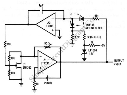
This is a quartz-stabilized oscillator circuit with electronic gain control. Replacing the common filament lamp for amplitude stabilization, this circuit uses... This circuit represents a quartz-stabilized oscillator featuring electronic gain control, which enhances the stability and precision of the output...
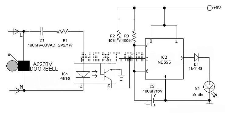
This 6V battery-operated doorbell light circuit can be connected in parallel with any existing AC 230V doorbell. When the doorbell switch is pressed, the bell sounds as usual, and the AC mains supply available across the doorbell is routed...
The circuit is composed of a 555 oscillator and an amplifier driver stage. It includes the 555 timer along with resistors R1, R2, RP1, capacitor C1, and other components forming a multi-harmonic oscillator. The frequency can be adjusted using...
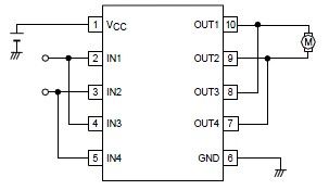
A simple forward-reverse motor control driver electronic circuit can be designed using the LB1948M, a two-channel low saturation voltage forward-reverse motor control driver IC. The LB1948M motor driver is suitable for use in 12V system products and can drive...
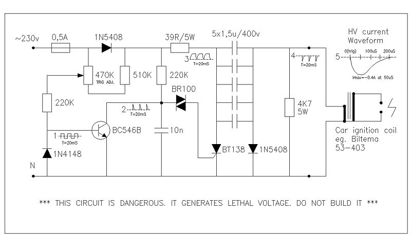
This circuit generates high voltage pulses from a 230 VAC line voltage. The drive end's swing comparator circuit was developed by the creator of this page. The working end is derived from a stroboscope trigger supply circuit. All circuits...
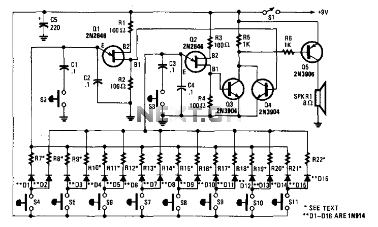
The electronic bagpipe simulates the sound of actual instruments. This circuit employs two UJT oscillators and an amplifier (Q3, Q4, and Q5). Resistors R7 to R22 are chosen to achieve the desired tonal range (typically between 3 to 300)....
Warning: include(partials/cookie-banner.php): Failed to open stream: Permission denied in /var/www/html/nextgr/view-circuit.php on line 713
Warning: include(): Failed opening 'partials/cookie-banner.php' for inclusion (include_path='.:/usr/share/php') in /var/www/html/nextgr/view-circuit.php on line 713