
Industrial Building Automation System (IBAS) - 4
 - 4")
The circuit involves two optical sensors that are strategically positioned to monitor the entrance of individuals. These sensors operate by emitting light and detecting interruptions caused by a person passing through their field of view. When a person enters the detection zone, the sensor generates a high-to-low pulse signal. This pulse is then sent to the microcontroller, which processes the data to maintain an accurate count of the individuals entering.
The microcontroller is programmed to interpret the pulse signals received on its input pins, specifically A3 and A4. Each time a pulse is detected, the microcontroller increments a counter that tracks the total number of individuals who have entered the monitored area. This count is subsequently transmitted to a secondary microcontroller, designated as MCU-II, for further processing or display.
The schematic design should include the optical sensors connected to the designated input pins of the microcontroller, ensuring that proper pull-up or pull-down resistors are employed as necessary to stabilize the input signals. Additionally, power supply considerations for both the sensors and the microcontroller must be addressed to ensure reliable operation. The communication protocol between the microcontroller and MCU-II should be defined, which may involve serial communication or another suitable method for data transfer.
Overall, the circuit design must prioritize accuracy in person counting, responsiveness to the sensor signals, and reliable communication between the components to achieve the intended functionality.The two optical sensors will give person count to the microcontroller and microcontroller will give this value to MCU-II. The microcontroller will sense the entrance of any person from high to low pulse on input pins (A3 and A4)
🔗 External reference
Related Circuits
Assistance is requested for building a square wave generator. The design should include a control for variable frequency ranging from 1 Hz to 200 Hz, as well as a switchable voltage feature. The square wave generator circuit can be designed...
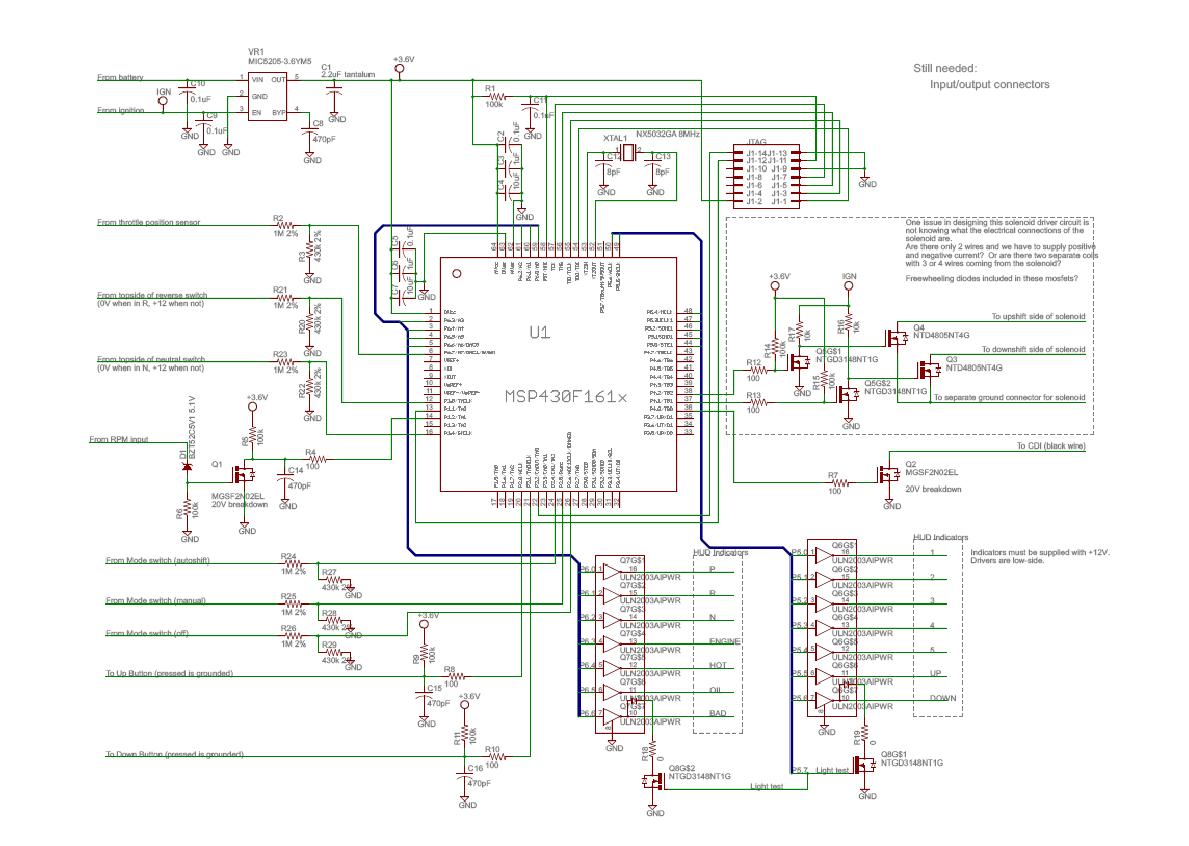
The following data and mapping pertain to the 2-D shift mapping algorithm that the controller will utilize to determine when and if a shift should occur. The solid lines on the graph indicate up-shift boundaries, while the dashed lines...
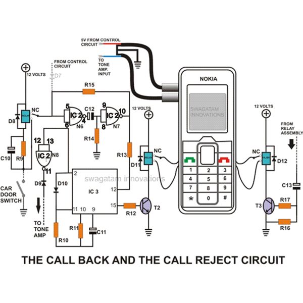
This homemade GSM car security system features a straightforward circuit design that effectively operates as a GSM car security system. The homemade GSM car security system employs a simple yet effective circuit design that integrates a GSM module, microcontroller, and...
The CYB-P51 (Rev A) Prototyping Board is designed as a two-layer board without dedicated power and ground planes. All components, except for the premounted P-51, utilize through-hole technology for ease of probing and part replacement. The board features an...

An LM2808 performs IF amplification of the 4.5-MHz sound subcarrier, limiting, detection, and audio amplification. If the center frequency must be changed, then change L1/C4. Audio output is 0.5 W. R3 is the volume control. The LM2808 is an integrated...
Feedback in a public address amplifier should be avoided. The ideal solution is to adjust the positions of the microphone and speaker; however, this is not always feasible in many situations. A frequency shifter that alters the output frequency...