
Building a square wave generator

The square wave generator circuit can be designed using a 555 timer IC in astable mode, which is a common approach for generating square waves. The frequency of the output square wave can be adjusted using resistors and capacitors connected to the timer.
To achieve the desired frequency range of 1 Hz to 200 Hz, the timing components must be selected carefully. The frequency (f) of the output square wave in astable mode is given by the formula:
f = 1.44 / ((R1 + 2*R2) * C)
Where:
- R1 is the resistor connected between the discharge pin and Vcc.
- R2 is the resistor connected between the discharge pin and the threshold pin.
- C is the timing capacitor connected from the threshold pin to ground.
To allow for frequency variation from 1 Hz to 200 Hz, a potentiometer can be used in place of R2, enabling fine-tuning of the frequency. Additionally, a fixed resistor R1 can be chosen to set a minimum frequency, while the potentiometer allows for adjustment to reach the maximum frequency.
For the switchable voltage feature, a voltage divider or an adjustable power supply can be implemented. A rotary switch can be used to select different resistor values or configurations to change the output voltage levels. This will allow the user to switch between various voltage outputs as required by the application.
The output from the 555 timer can be fed into a buffer or amplifier circuit if higher current output is needed. This design will ensure that the square wave generator meets the specified requirements for frequency control and voltage adjustability, making it suitable for a variety of applications. Proper attention should be given to component ratings and tolerances to ensure reliable operation across the entire frequency range.Hope someone can help me. I want to build a square generator. I want it to have control for frequency variable 1hz to 200hz, a switchable voltage.. 🔗 External reference
Related Circuits
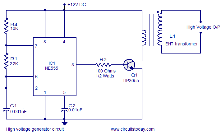
This circuit is highly dangerous due to its output voltage, which is in kilovolts and poses a significant risk of serious injury or death. It should only be attempted by individuals with extensive experience in handling high voltages. No...
At VHF, both the 1/4-wavelength monopole and the 5/8-wavelength monopole antennas are widely used. The VHF 5/8-wavelength (144 MHz) vertical monopole has long held the reputation of providing about a 3-dB gain advantage over the 1/4-wavelength vertical monopole. The...
The closed-loop system consists of longitudinal and transverse components. The circuit operates as follows: a control circuit from the stepping motor CNC system issues a command, which the receiver detects. This signal is processed through a phase-sensitive rectifier to...
Sensitivity and selectivity are important factors for a shortwave listener considering the purchase of a new receiver. While commercially available communications equipment can meet expectations, such products tend to be expensive. Low-cost alternatives often involve homebrewed radios, with the...
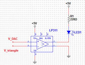
A pulse-width modulated (PWM) signal can be generated using a triangle wave and a comparator. The digital-to-analog converter (DAC) serves as the input signal, and the resulting output signal's duty cycle will be proportional to the input voltage. This...
This type of design can generate a very high amperage current for a fraction of a second, which can be utilized for various applications if properly harnessed. The switching device could be a rotating spark gap, as utilized by...