Infrared Alarm Barrier Circuit
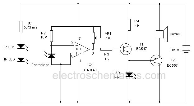
This infrared alarm barrier is designed to detect individuals passing through doorways, corridors, and small gates. The transmitter emits an infrared light beam that is not visible to the human eye. When the beam is interrupted by a person, the buzzer connected to the receiver is activated. The transmitter and receiver circuits of this infrared alarm system are engineered to operate over several meters, remaining effective under varying ambient light conditions. In rare instances where the receiver sensor is subjected to bright, direct sunlight, additional shielding may be necessary. The transmitter emits a modulated infrared signal rather than a continuous one; it utilizes a 36-kHz carrier frequency that pulses the infrared emitting diode (IRED) on and off at approximately 300 Hz. This modulation is crucial because most infrared sensors, including those depicted in the schematic, do not perform optimally with continuous infrared exposure. By intermittently switching off the IR source, the detectors can recover, thereby enhancing their ability to ignore ambient light. The transmitter is constructed using two oscillators based on the widely used 555 integrated circuit (IC). The current-efficient CMOS version, TLC555 (or 7555), is employed, although the two 555 ICs can be substituted with a single TLC556 (or 7556). IC1 functions as the 300-Hz generator, while IC2 serves as the 36-kHz source. The IRED, specifically the LD274 type, is pulsed at a relatively high peak current through the driver transistor T1. If the application requires a shorter IR beam distance, the value of resistor R5 can be increased to reduce current consumption. The preset P1 is calibrated to achieve an exact carrier frequency of 36 kHz; in the absence of testing equipment, it should be adjusted for optimal range. The receiver circuit is also straightforward and based on a CMOS 555 IC. While the sensor detects infrared light from the transmitter, the reset input of the 555 IC remains low, keeping the buzzer silent. Components D1 and C2 function as a low-frequency rectifier, mitigating the impact of the 300-Hz modulation on the transmitter signal. When the infrared beam is disrupted, the oscillator associated with the 555 IC is triggered, generating a warning tone. The test values indicated in the infrared barrier alarm circuit diagram represent average DC levels measured with a digital voltmeter (DVM) under both light and no-light conditions. Most test points reflect rectangular or sawtooth waveforms.
The infrared alarm barrier circuit is a practical solution for enhancing security in various environments. The design leverages the 555 timer IC's versatility, allowing for precise frequency generation and modulation control. The use of the TLC555 variant ensures lower power consumption, making the system suitable for battery-operated applications. The modulation scheme employed not only improves the sensitivity of the infrared sensors but also reduces false triggers caused by ambient infrared sources, such as sunlight or artificial lighting.
The transmitter's pulsing mechanism can be fine-tuned using the preset resistor, allowing for adaptability in different operational ranges. This feature is particularly useful in environments where the distance between the transmitter and receiver may vary. The receiver's simplicity ensures ease of integration into existing systems, while the buzzer provides immediate feedback upon detection of an intrusion.
Overall, this infrared alarm barrier circuit exemplifies an effective balance between performance and energy efficiency, making it a valuable component in modern security systems. The straightforward design facilitates easy assembly and maintenance, while the use of common components ensures cost-effectiveness.This infrared alarm barrier can be used to detect persons passing through doorways, corridors and small gates. The transmitter emits a beam of infrared light which is invisible to the human eye. The buzzer at the output of the receiver is activated when the light beam is interrupted by a person passing through it.
The transmitter and receiver circ uits of the infrared alarm system shown here have been designed for a range of several meters, almost independent of ambient light conditions. Only in the rare case of the receiver sensor being exposed to bright, direct sunlight, some screening measures have to be added.
The transmitter does not emit a continuous infrared signal, Rather, it is modulated, that is, the 36-kHz carrier used to pulse the IRED (infrared emitting diode) on and off is itself switched on an off at a rate of about 300 Hz. The reason for doing so is that most infrared sensors, including the ones suggested in the diagram do not respond very well to continuous incidence of infrared light.
Switching the IR source off, even for a small period, allows IR detectors to recuperate`, and so optimise their ability to minimize the response to ambient light. The transmitter consists of two oscillators built around the ubiquitous 555 IC. Here, the current-saving CMOS version TLC555 (or 7555) is used. Alternatively, the two 555`s may be replaced by a single TLC556 (or 7556). IC1 is the 300-Hz generator, IC2, the 36-kHz source. The IRED type LD274 is pulsed at a relatively high peak current via driver transistor T1. If in your application the distance covered by the IR beam is relatively short, the value of resistor R5 may be increased to save on current consumption.
Preset P1 is adjusted for a carrier frequency of 36 kHz exactly (failing test equipment, adjust it for optimum range). The receiver is equally simple and also based on a CMOS 555. As long as the sensor picks up infrared light from the transmitter, the reset input of the 555 IC is held low and the buzzer is silent.
Components D1 and C2 act as a low-frequency rectifier to cancel the effect of the 300-Hz modulation on the transmitter signal. When the infrared light beam is interrupted, the oscillator built around the 555 is enabled and starts to produce a warning tone.
Finally, the test values indicated in the infrared barrier alarm circuit diagram are average dc levels measured with a DVM, under light/no light conditions. In fact, most test points carry rectangular or sawtooth waveforms. 🔗 External reference
