
Infrared Alarm

The circuit described features a basic infrared (IR) communication system, which is divided into a transmitter and a receiver section. The transmitter is built around an LED (LED1), which emits infrared light when activated. The second part of the circuit includes a photodiode or phototransistor that acts as the receiver, detecting the IR signal transmitted by LED1.
In the transmitter section, when the switch S1 is pressed, it completes the circuit, allowing current to flow through LED1. The LED emits infrared light, which can be directed towards the receiver. The intensity of the emitted light can be adjusted using a variable resistor (R6). This adjustment is crucial for ensuring that the signal strength is adequate for reliable detection by the receiver.
The receiver section is designed to sense the IR light emitted by the transmitter. When the photodiode or phototransistor detects the IR light, it generates a corresponding electrical signal. This signal is used to trigger a relay, which can be employed to control larger loads or provide an output indication.
To optimize the performance of the circuit, especially in terms of range, it is recommended to use a high-output LED for LED1. This choice enhances the transmission distance, allowing the signal to be detected from further away. However, it is important to note that ambient bright light can interfere with the operation of the receiver, potentially causing it to fail to respond to the transmitter's signal. Therefore, careful placement and adjustment of the circuit components are necessary to mitigate this issue.
The use of printed circuit boards (PCBs) for this design simplifies the assembly process, providing a structured layout for the components, which aids in minimizing errors during construction and ensures reliable operation. The PCBs can be designed to accommodate all necessary components, including the LED, relay, resistors, and any additional supporting circuitry required for optimal performance.This circuits consist of two parts, the first part will transmit a signal, and the second part will detect that signal and trigger a relay.To adjust the circuit, hold down S1 while pointing LED1 at the receiver. Adjust R6 until you hear the relay click. You can increase range by using a high output LED for LED1. Bright light will stop the receiver from responding to the transmitter. You can use the designed PCBs to build the circuit simply: 🔗 External reference
Related Circuits
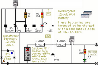
The following circuit illustrates an Alarm Power Supply Circuit Diagram. Features include a 1-amp current output, suitable for a Modular Burglar Alarm operating at 12 volts. The Alarm Power Supply Circuit is designed to provide a stable and reliable power...

The mute pin of this dual audio amplifier serves as the trigger for a single-chip high-temperature alarm. One half of the integrated circuit (IC) functions as an oscillator, while the other half amplifies the audio alarm outputs to 10W. The...

The danger always exists when fuel gases such as propane or natural gas are confined to a small area. The toxic gas alarm utilizes a tin-oxide semiconductor. A coil of thin wire is heated by a 12 V battery...
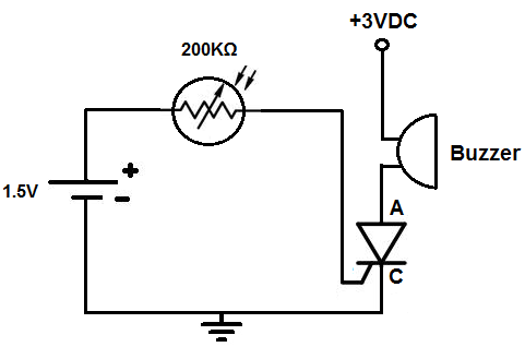
This circuit activates an alarm when tilted beyond a specific angle. Commonly used in various electronic devices, such as heaters, tip-over protection circuits can either shut off the device or trigger an alert. In this case, the circuit is...
The photodiode is utilized to detect infrared (IR) light reflected from an object. However, it also picks up IR light generated by ambient conditions, which can lead to false detections. To mitigate this issue, it is essential to filter...
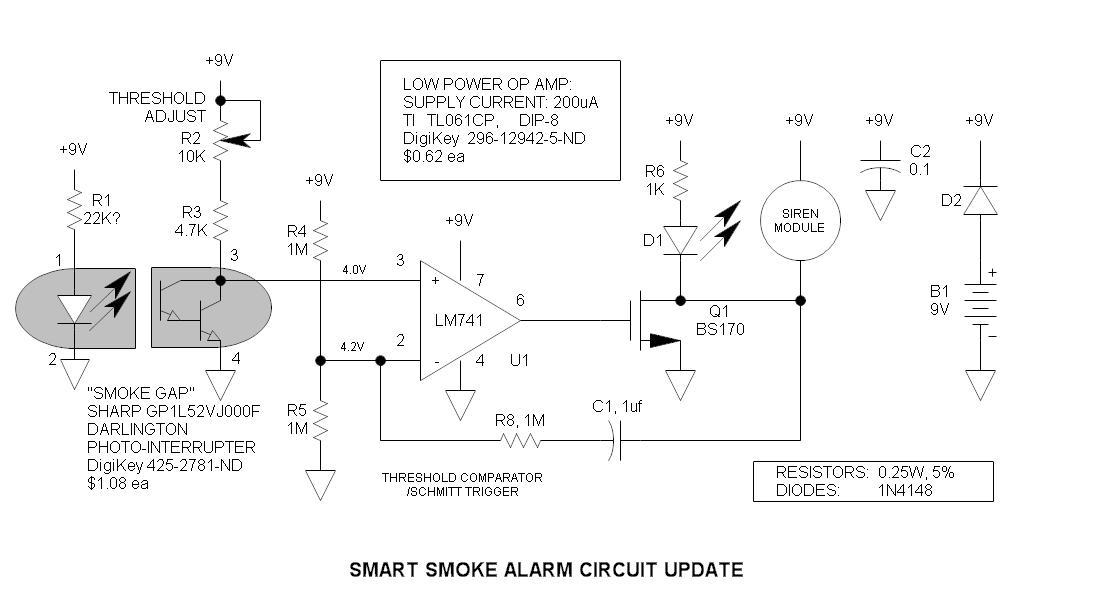
The original smoke alarm circuit has several issues that have left hobbyists and students dissatisfied. Instead of trying to resolve its numerous problems, an updated version has been created using the well-known LM741 op-amp. This new design is simpler,...