
Temperature alarm

The dual audio amplifier described utilizes a mute pin that acts as a trigger for a high-temperature alarm system. This configuration allows for the integration of temperature monitoring and audio alert functionalities within a single device. The oscillator section of the IC is responsible for generating a specific frequency signal, which can be tuned to activate the alarm under predefined temperature conditions.
The second half of the IC is designed to amplify the audio output, ensuring that the alarm is sufficiently loud to alert nearby individuals. With an output power capacity of 10W, this amplifier can drive a speaker or buzzer effectively, making it suitable for various applications, including industrial equipment monitoring, HVAC systems, or any environment where temperature control is critical.
When the temperature exceeds a certain threshold, the mute pin is activated, allowing the oscillator to initiate the alarm signal. This dual functionality not only enhances the efficiency of the system but also reduces the need for multiple discrete components, leading to a more compact and cost-effective design.
In summary, the described circuit integrates temperature sensing and audio alert capabilities into a single dual audio amplifier IC, leveraging its oscillator and power amplification characteristics to provide an effective solution for high-temperature alarm systems.The mute pin of this dual audio amplifier is used as the trigger for a one chip high-temperature alarm. One-half of the IC is connected as an oscillator and the other boosts the audio alarm outputs to 10W.
Related Circuits
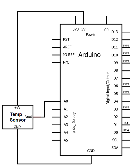
The integrated circuit (IC) used for temperature measurement is the TMP36. This IC will be integrated with an Arduino to obtain temperature readings. The Arduino will read the measured value from the TMP36 and convert it into degrees Fahrenheit,...
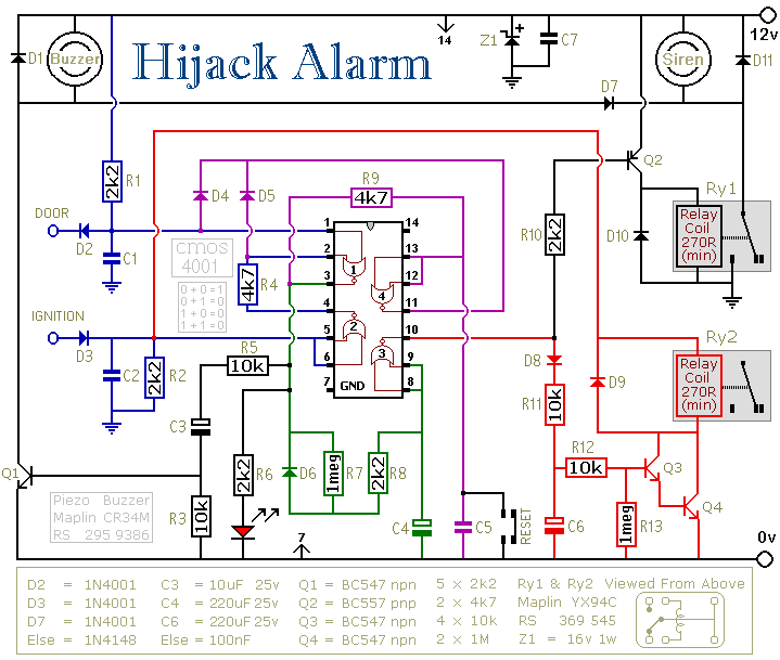
The first circuit is designed for situations where a hijacker forces the driver from the vehicle. If a door is opened while the ignition is switched on, the circuit will activate. After a few minutes delay, when the thief...
The ROMs or PROMs must contain the correct code to convert data from the NE5037, which serves as the address for the ROMs or PROMs, into the appropriate segment driver codes. The displayed temperature can easily be converted to...
The locker alarm circuit, also known as the cashbox watcher, is designed to safeguard a cashbox or locker from unauthorized access. This reliable design features a foolproof, remotely operated alarm and electromagnetic relay driver that receives its control signal...
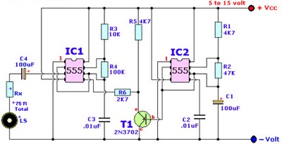
Browse home alarm circuit explanation latest schematic siren wailing with latest Wailing Alarm Siren circuit schematic with explanation. The loudspeaker LS and the resistor marked Rx should be together 75 ohms. If a standard 8-ohm speaker is used, then...
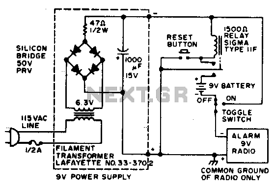
In the event of a power failure, the radio alarm activates without producing a loud siren, bell, or whistle. The alarm remains active even after power is restored and will continue until the RESET button is pressed. The described circuit...