
infrared emitter and detector using ic 74ls14

The line detection circuit primarily employs an infrared (IR) transmitter and receiver configuration, where the IR LED emits light that reflects off surfaces and is detected by a phototransistor. The effectiveness of this setup hinges on the alignment and calibration of the components. The IR light's reflection characteristics can vary based on the surface properties of the detected object, necessitating adjustments to the sensitivity of the phototransistor.
To enhance the circuit's functionality, it may incorporate a microcontroller to process the signals from the phototransistor. This microcontroller can analyze the received signals and determine whether an object is present based on the intensity of the reflected IR light. The logic can be programmed to trigger specific actions, such as stopping the robot or navigating around obstacles.
For calibration, the circuit should include variable resistors to adjust the sensitivity of the phototransistor. This allows for fine-tuning based on environmental conditions and the specific characteristics of the surfaces being detected. Moreover, the use of a laser pointer can improve detection accuracy over longer distances, providing a clear and focused beam that enhances the reliability of the detection mechanism.
In practical applications, the circuit can be integrated into a mobile robot platform, enabling it to navigate autonomously while avoiding obstacles. The simplicity of the IR transmitter and detector pair makes it an accessible choice for hobbyists and professionals alike, while the potential for expansion through microcontroller integration allows for more complex behaviors and functionalities in robotic systems.This circuit have applied to line detection of robot project, Good match between the transmitter and the detector is important for proper operation, especially if the hole is large. Robot with a simple object or obstacle detection. Infrared Transmitter detector pair sensors are relatively easy to implement, although involved some degree of testing
and calibration in order to make correct. They can for the impediment, motion detection, transmitters, encoders are used, and the color detection. This can be done with a piece of rope stretched between and in accordance with LED and phototransistor.
A length of stiff wire or plugs can be used to set the alignment. Another method that can be used for long distances is a laser pointer shone through a hole. 🔗 External reference
Related Circuits
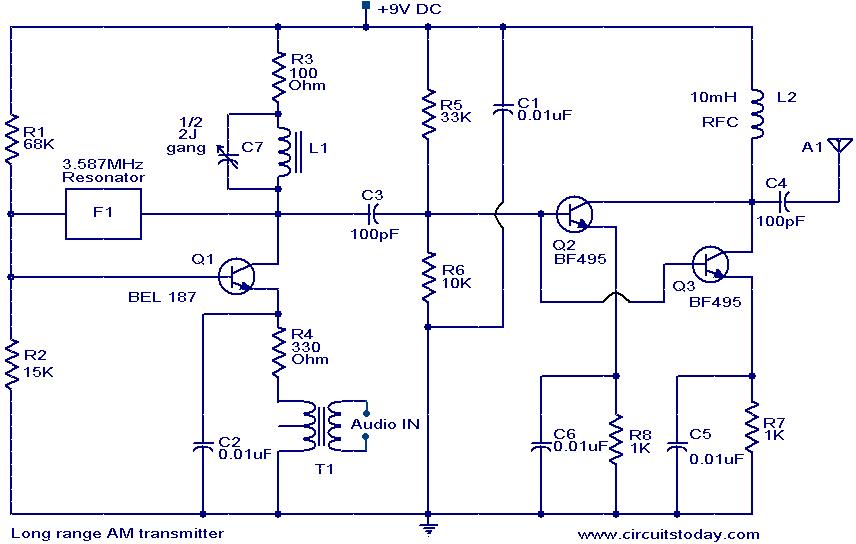
The circuit diagram of an AM transmitter circuit based on three transistors. With correct tuning and a matching antenna, the transmitter can effectively transmit amplitude-modulated signals. The AM transmitter circuit utilizes three transistors configured to amplify and modulate the input...
%2Bwith%2Banimation%2Bsimulation%2Bcircuit.png)
The Johnson digital counter, also known as the Twisted Ring Counter, is a synchronous shift register that incorporates feedback from the inverted output (Q`) of the last flip-flop. The Q` output of the final flip-flop is connected back to...

Introduction The design of off-line constant voltage, constant current (CVCC) power supplies using the NCP1014 for devices such as cell phones, hand tools, and similar battery chargers can present various challenges when low cost and circuit simplicity are required...
Introduction The ignition timing lights commonly used range from simple neon to complex units. Neon timing lights have a drawback due to their low light output, necessitating operation in subdued lighting. This presents a safety hazard, as users tend...
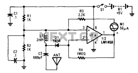
This detector is a half-wave rectifier for RF, which then feeds an operational amplifier. U1A acts as an amplifier, driving meter M1. This circuit can detect milliwatt RF levels from below the AM broadcast band to well above the...
This circuit is designed for liquid level or proximity detection. It operates by measuring the distance to a target through the reflection of an infrared beam. The device can detect the level of liquid in a tank without any...