
infrared receiver ir rx output waveform

The circuit setup involves an infrared transmitter and receiver, which utilize diodes to function as their respective antennas. The infrared transmitter emits modulated light signals, which are detected by the IR receiver. The iMSO-104 oscilloscope is connected to the output of the receiver to visualize the signal strength and waveform characteristics. The oscilloscope is capable of capturing and displaying multiple traces, allowing for comparative analysis between the reference signal and the active measurement signal as the transmitter is rotated.
The reference trace serves as a baseline for evaluating signal integrity, while the active trace illustrates the variations in signal strength as the alignment changes. The peak-to-peak voltage of the waveform is a critical parameter, as it indicates the strength of the received signal. When the transmitter is perfectly aligned with the receiver, the output voltage is maximized, demonstrating optimal performance.
The setup also includes a comparator circuit that monitors the output voltage of the receiver. When the signal falls below a set threshold, the comparator activates an alarm, providing an audible indication of signal loss. This functionality is essential for applications where maintaining a reliable link between the transmitter and receiver is critical.
Future experiments could explore the effects of varying distances between the transmitter and receiver while maintaining alignment, which would provide further insights into the operational range and limitations of the IR communication system. The use of the iMSO-104 oscilloscope facilitates detailed analysis of the waveform characteristics, enabling the evaluation of performance metrics in real-time.In the picture above, Oscium`s iMSO-104 oscilloscope is measuring the output waveform of an infrared receiver (IR Rx). The iPad and iMSO are functioning as the oscilloscope for measuring the receiver`s output signal as the relative alignment between transmitter and receiver varies.
There are two waveforms captured on the oscilloscope screen. Trace 1, the Reference trace (in grey) is the full scale Rx output from a 0 degree, on axis Rx/Tx alignment. The active measurement trace (in green) is being measured as the IR transmitter is rotated off axis with the receiver. You can witness this action in this short video clip complete with audio. Turn up your speakers! The infrared transmitter and receiver are set 12-18 apart from each other on a flat, horizontal surface.
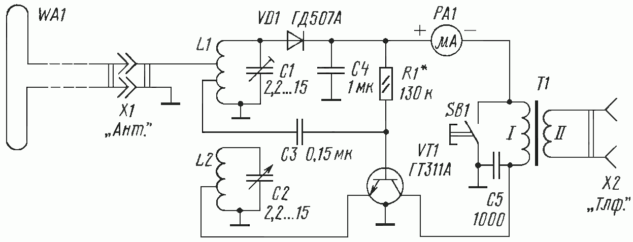
When you think about signal strength for wireless devices like cell phones, radios, televisions, and satellites, you think of how the antennas on the receiver and transmitter units are aligned. For this application, however, we don`t have antennas. Instead of parabolic dishes, weird metal shapes etched in a circuit board, or telescoping wands that are mechanical structures obviously functioning as antennas, the infrared receiver and transmitter units rely on a special class of diodes for their antennas.
The figure below shows the oscilloscope screen displaying the strongest and weakest signals measured at the receiver`s output without triggering the alarm. When the transmitter is perfectly aligned with the receiver, the output waveform`s peak-to-peak voltage is at its maximum value.
I used the oscilloscope`s reference capture function to save the trace and preserve it for display on the screen. As demonstrated in the video clip, I can rotate the transmitter about thirty degrees off axis from the receiver before tripping the receiver`s alarm.
I`ve superimposed the arc or rotation in the picture of the setup for this experiment for reference. When the received signal decays to a predefined limit, a comparator voltage trips and turns on the buzzer.
A follow on experiment to what I`ve done here would be to move the two units apart horizontally, keeping them aligned, and see how far apart they can be while maintaining sufficient signal strength. The IR Rx/Tx kit used for this post is available at any Radio Shack. Click here to follow a link to the product page on Radio Shack`s website. The team at Oscium would like to hear about your own experiements, so please let us know. 🔗 External reference
Related Circuits
A series capacitor is most effective for low impedance loads, while a parallel capacitor is utilized for high impedance loads. The current standard is a 50-ohm antenna and coax system that requires a series capacitor for loading adjustment. With...
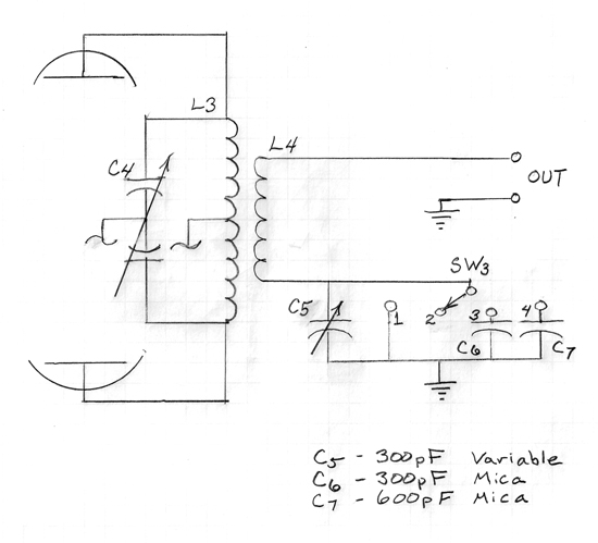
The concept of a "crystal radio" is typically linked with large antennas and radio broadcasting on long and medium bands. This article discusses experimentally tested detector circuits for VHF receivers designed to listen to FM stations. The discovery of...
This application note explains the operation of the data slicers found in the Maxim line of UHF receivers such as the MAX1470, MAX1473, and MAX1471, as well as transceivers like the MAX7030 and MAX7032. The data slicers in the Maxim...
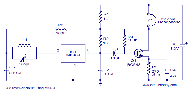
A cost-effective and straightforward AM receiver circuit utilizing the MK484 integrated circuit. The circuit requires minimal external components and operates within a frequency range of 150 kHz to 3 MHz. The MK484 AM receiver circuit is designed for simplicity and...
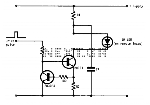
Q1 and Q2 form a constant current drive defined by R2. The current (I) approximates the reciprocal of R2 in the circuit shown for values of I greater than 1 amp. The pulse current is drawn from C1, which...
The regen is basically an oscillator circuit with a gain control that allows the user to adjust the feedback to a point just below oscillation or, quite often, just above the critical level such that a small oscillation is...