
Infrared Intruder Alarm

The Infrared Intruder Alarm circuit operates by utilizing infrared (IR) sensors to detect motion within a designated area. The basic components of this circuit typically include an IR transmitter and receiver pair, a microcontroller or an operational amplifier, a power supply, and an alarm output device such as a buzzer or LED indicator.
In operation, the IR transmitter emits infrared light, which is reflected off objects within the detection zone. The IR receiver detects this reflected light. When a person or object enters the detection area, the reflected IR light is interrupted, causing the receiver to trigger a response. This interruption can be detected by the microcontroller, which processes the signal and activates the alarm output.
The circuit can be designed to include adjustable sensitivity settings, allowing users to customize the detection range according to their needs. Additionally, the use of resistors and capacitors can help stabilize the circuit and prevent false alarms caused by ambient light changes or other environmental factors.
For enhanced functionality, the circuit may incorporate features such as a delay timer to prevent the alarm from sounding immediately after detection, allowing for a grace period for authorized individuals. Moreover, incorporating a wireless transmission module can enable remote monitoring and notifications, providing an added layer of security.
Overall, the Infrared Intruder Alarm circuit presents a reliable and effective solution for security applications, ensuring that unauthorized access is promptly detected and reported.circuit Infrared Intruder Alarm This the circuit warns the trespasser infrared system or Infrared Intruder Alarm circuit that interesting. By when there is a. 🔗 External reference
Related Circuits
The project involves bypassing the mechanical snooze switch of an alarm clock and replacing it with a more engaging method: physically striking the device. The objective is to impart useful techniques in reverse engineering that can be applied to...

A few months ago, a compact and effective alarm was designed with the following requirements: simple construction, reliable operation, low power consumption, and a small size. Initially, CMOS logic gates were considered, but this approach was abandoned due to...
The simplified block diagram of a high-sensitivity alarm circuit features a photoresistor (LDR) and three ordinary resistors connected in a specific configuration. When transitioning from complete darkness to full light, the potential at point X varies between approximately 1/4...
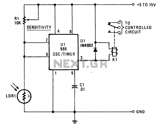
LDR1, a cadmium sulfide (CDS) photoresistive cell, is utilized as the lower leg of a voltage divider between Vcc and ground. The timer terminals 2 and 6 are connected to the junction of the photocell and the sensitivity control...
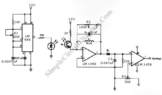
The infrared transmitter and receiver circuit depicted in the schematic diagram can function as a remote control system. The transmitter operates as an oscillator circuit, with the frequency adjustable through the R1 potentiometer (or trimmer pot). This oscillation ensures...

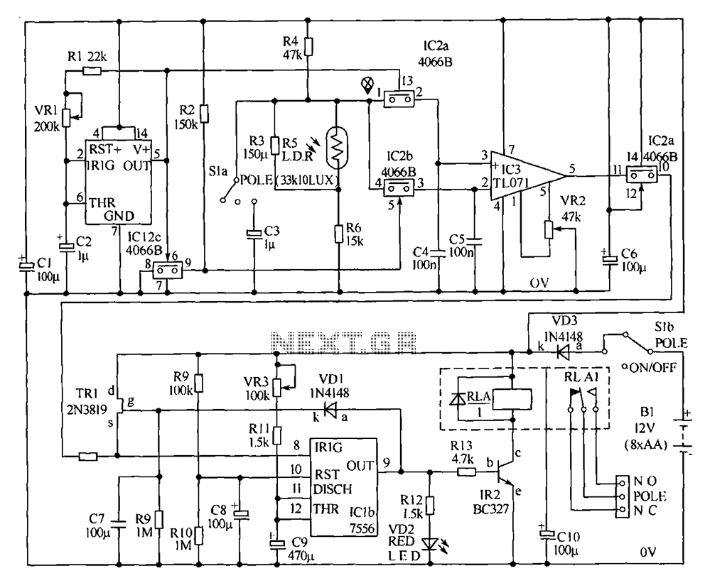
This circuit features open and closed loop contacts (switches 1, 2, 3) that activate the alarm, which remains on for a duration of 5 to 10 minutes. The triggering delay for entrance and exit is set to 27 seconds....